What FTK Imager Is Used For in a Workflow
FTK Imager is a Windows-based acquisition and preview tool commonly used to create forensic images of disks, partitions, removable media, and selected logical data. In a forensic imaging workflow, it helps you (1) identify the correct source, (2) capture a bit-for-bit image or a targeted logical collection, (3) generate acquisition logs and image metadata, and (4) verify the resulting image by comparing computed values before and after acquisition. This chapter focuses on practical workflows inside FTK Imager: choosing the right acquisition type, configuring image formats, handling large drives, and producing artifacts (images, logs, and reports) that are easy to validate and easy to hand off for analysis in other tools.
Pre-Acquisition Setup: Prepare the Workstation and Storage
Decide where the image will be written
Before opening FTK Imager, decide on a destination storage location that is separate from the source you are imaging. In practice, this is usually an external evidence drive or a dedicated acquisition SSD connected to your forensic workstation. Ensure the destination has enough free space for the image plus overhead (logs, possible compression differences, and split segments). As a rule of thumb, plan for at least the size of the source for raw images, and still plan close to source size even when using compression because compression is not guaranteed.
Stabilize the environment
Close unnecessary applications, disable sleep/hibernation, and ensure the workstation is on reliable power. Imaging is I/O intensive and can take hours; interruptions can cause partial images and wasted time. If you are acquiring from a laptop drive via an adapter, ensure the adapter is stable and not power-starved. If you are acquiring from USB media, use a high-quality port and cable to reduce disconnect risk.
Write-blocking considerations (workflow focus)
FTK Imager can be used with hardware write blockers for physical drives. In a workflow, the key operational point is to confirm the source is presented read-only before you begin acquisition. Many labs rely on a hardware write blocker for SATA/NVMe-to-USB bridges, while for removable media they may use a read-only switch (when available) plus careful verification. The goal in this chapter is not to re-teach the theory, but to emphasize the practical step: confirm the source is not writable from the acquisition workstation before you click “Start.”
Tour of FTK Imager Features You Will Use Most
Evidence Tree and Preview Pane
When you open FTK Imager, you can add evidence items (physical drive, logical drive, image file, folder, or individual files). The Evidence Tree shows detected devices and volumes; the preview pane lets you quickly view file content and metadata. In imaging workflows, this preview is useful for confirming you selected the correct device (for example, verifying volume labels, partition sizes, and expected folder structure) before acquisition.
- Listen to the audio with the screen off.
- Earn a certificate upon completion.
- Over 5000 courses for you to explore!

Download the app
Creating Images vs. Adding Evidence
Adding evidence items is for preview and triage; creating an image is the acquisition step. A common beginner mistake is to add a physical drive to the Evidence Tree and assume that action “captured” it. It did not. You must use the Create Disk Image function to produce an image file (or set of segments) that can be analyzed later without the original device.
Capture Memory (RAM) option
FTK Imager includes a memory capture feature. This chapter focuses on disk imaging workflows, but it is important to recognize that RAM capture is a separate acquisition type with different storage sizing and timing considerations. If your case plan includes memory, treat it as its own acquisition step with its own output file and log.
Choosing the Right Acquisition Type in FTK Imager
Physical Drive imaging (bit-for-bit)
Physical drive imaging captures the entire device, including unallocated space and typically all partitions. Choose this when you need the most complete representation of the storage device, such as for full examinations, recovery of deleted artifacts, or when you cannot predict which partitions contain relevant data. In FTK Imager, this is usually the default choice for internal HDDs/SSDs and many removable drives.
Logical Drive imaging (volume-level)
Logical drive imaging targets a specific volume (for example, C:). This can be appropriate when you only have access to a mounted volume and cannot access the underlying physical disk, or when scope is limited to a particular partition. Be aware that logical imaging may not include all unallocated space outside that volume and may omit other partitions.
Image selected folders/files (logical collection)
FTK Imager can also collect selected folders and files into an evidence container. This is useful for rapid triage or when you have explicit scope limitations. The tradeoff is completeness: you will not capture deleted data outside the selected items, and you may miss artifacts stored elsewhere (for example, in system directories you did not select). Use this option when the investigative plan explicitly calls for targeted collection.
Step-by-Step: Create a Physical Drive Image (Common Workflow)
Step 1: Identify the correct source disk
Open FTK Imager and go to File > Create Disk Image. Choose Physical Drive. You will see a list of available physical devices. Carefully identify the correct disk by capacity, model, and interface. If you have multiple similar drives connected, disconnect non-essential devices to reduce the chance of selecting the wrong source.
Step 2: Select the image type (format)
FTK Imager typically offers formats such as:
- Raw (dd): A straightforward bitstream image. Highly compatible and simple, but can be large and may not store rich metadata in the same way as container formats.
- E01 (EnCase Evidence File): A common forensic container format that supports compression, segmentation, and embedded metadata. Frequently used for lab workflows and tool interoperability.
- SMART (S01): Another container format with similar goals (compression/segmentation/metadata), used in some environments.
Choose based on your lab’s standard and downstream tooling. If you expect to share the image with other examiners or tools, E01 is often a safe choice. If you need maximum simplicity and compatibility with low-level tools, raw may be appropriate.
Step 3: Enter case and evidence metadata
FTK Imager prompts for information such as case number, evidence number, examiner, and notes. Fill these fields consistently. Treat this as operational metadata that helps others understand what the image is and where it came from. Use notes to record practical details that matter later, such as “Source: Dell Latitude SSD via write blocker, USB bridge model XYZ.”
Step 4: Configure destination, naming, and segmentation
Choose a destination folder on your acquisition drive. Use a naming convention that is unique and stable, for example: CASE123_EVID04_PhysicalDrive0. Configure image fragmentation (splitting) if needed. Splitting is helpful when storing on file systems with file size limits or when you want manageable segment sizes for transfer. Common segment sizes are 2 GB or 4 GB, but choose based on your storage and transport needs.
Step 5: Choose compression and verification options
If using E01 or another container that supports compression, choose a compression level. Higher compression can reduce storage but may increase acquisition time. Enable verification if your workflow requires it; verification typically means FTK Imager will compute values and compare them to confirm the image matches the source. This adds time but increases confidence that the acquisition completed correctly.
Step 6: Start acquisition and monitor for errors
Start the imaging process. Monitor the progress window for read errors, bad sectors, or disconnect events. If errors occur, document them and consider whether you need a second pass, a different adapter, or a different imaging strategy. Some drives with failing media may require specialized handling; in such cases, your workflow may shift to a more fault-tolerant acquisition approach.
Step 7: Review the output artifacts
When imaging completes, confirm you have: (1) the image file(s) or segments, (2) the FTK Imager log/report, and (3) any additional metadata files created. Store these together in a structured folder. A practical structure might be:
CASE123\EVID04\ACQ\ images\ logs\ screenshots\Keep the acquisition log in the logs folder and consider saving a screenshot of the final completion window if your lab practice includes it.
Step-by-Step: Create a Logical Drive Image (Volume-Level Workflow)
When to use it
Logical drive imaging is useful when you only need a specific volume or when physical imaging is not feasible due to access limitations. For example, you may be allowed to image only the user’s data partition, or you may be working with a system where only a mounted volume is exposed.
Steps in FTK Imager
Go to File > Create Disk Image, choose Logical Drive, and select the correct volume (for example, C: or an external volume). Confirm the volume label and size. Then choose the image type (often E01), fill in metadata, choose destination and segmentation, and start acquisition. After completion, verify that the resulting image mounts or opens correctly in FTK Imager and that the expected top-level directories are present.
Step-by-Step: Targeted Collection of Folders and Files
Use cases and limitations
Targeted collection is often used for quick response or when scope is limited to specific artifacts such as browser history exports, specific project folders, or application logs. The limitation is that you are collecting what you can see and select; you may miss relevant data stored elsewhere or in unallocated space.
Workflow in FTK Imager
Add the relevant drive or folder as an evidence item. Navigate in the Evidence Tree to the folders/files you need. Use the option to add selected items to an evidence container (depending on FTK Imager version, this may be presented as creating an image of selected files). Name the output clearly, such as CASE123_EVID04_Targeted_UserProfile. Ensure the output includes a log that lists what was collected. After collection, open the container in FTK Imager to confirm the expected files are present and readable.
Working with Image Formats, Splits, and Storage Constraints
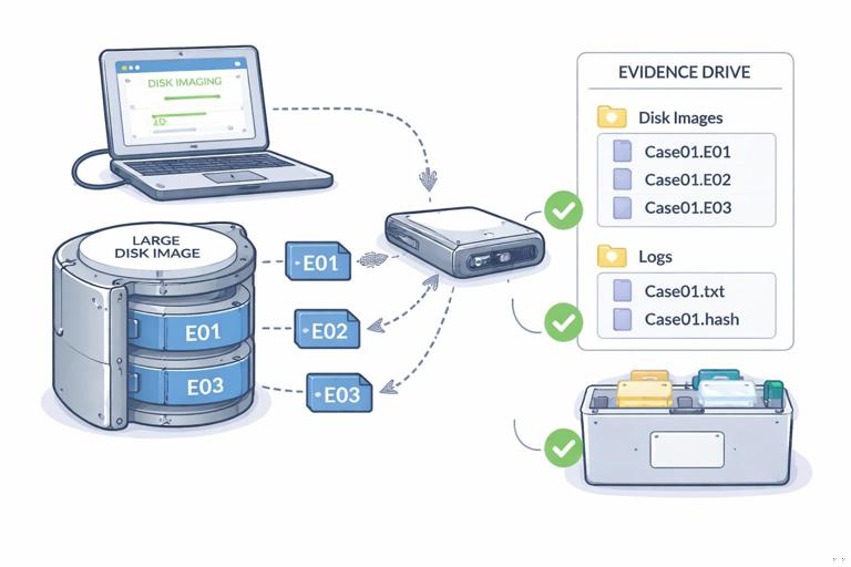
Segmented images and transfer reliability
Segmenting an image into multiple files can reduce the impact of a single file corruption during transfer and can fit storage constraints. For example, if you must store on a FAT32-formatted drive, you will hit file size limits quickly; segmentation becomes mandatory. Even when not required, segmentation can make copying and checksum verification easier in some workflows.
Compression tradeoffs
Compression can reduce storage usage, but it increases CPU load and time. If you are imaging many devices in a limited time window, you may choose low or no compression to prioritize speed. If storage is scarce and time is available, moderate compression can help. The key is to choose settings that align with operational constraints rather than assuming “maximum compression” is always best.
Choosing raw vs. E01 in practice
Raw images are simple and widely supported, but they can be cumbersome to manage for large drives because they are typically a single large file unless you manually split. E01 images are designed for forensic workflows with segmentation and metadata. If your downstream analysis toolchain expects E01, choose it to avoid conversion steps.
Handling Read Errors and Problem Drives During Imaging
Recognize symptoms early
During acquisition, watch for repeated read errors, extremely slow read speeds, or the device disconnecting. These can indicate failing media, unstable adapters, or power issues. If the device is failing, repeated attempts can worsen the condition, so plan your approach carefully.
Practical response options
- Change the connection path: Use a different cable, port, or adapter; connect directly via SATA when possible.
- Improve power stability: Use powered USB hubs for bus-powered devices if appropriate.
- Adjust expectations: If the drive has unreadable sectors, document the errors and understand that some data may be missing in the image.
FTK Imager will typically log read errors. Preserve those logs with the image so an examiner can interpret gaps or corrupted files during analysis.
Validation Checks Inside FTK Imager After Acquisition
Open the image and sanity-check the contents
After imaging, use File > Add Evidence Item and select Image File to load the newly created image. Expand the partitions/volumes and confirm that the structure matches expectations (for example, Windows directory present on a system volume, user profiles present on a data volume). This is not deep analysis; it is a quick confirmation that the image is readable and appears complete.
Confirm segment set integrity
If you created a segmented E01, ensure all segments are present in the same folder and named consistently. Missing a segment can prevent the image from opening or cause partial visibility. A practical habit is to sort by name and verify the sequence is continuous (for example, .E01, .E02, .E03, etc.).
Generating and Using FTK Imager Reports
What the report provides
FTK Imager can generate an acquisition report that includes details such as source device information, image type, segment size, timestamps, and any errors encountered. This report is a key operational artifact for communicating what was done during acquisition and for supporting later review.
Report handling workflow
Save the report in a dedicated logs folder alongside the image. Use a consistent filename, for example: CASE123_EVID04_FTKImager_AcquisitionReport.txt. If your workflow includes peer review, provide the report with the image so another examiner can quickly confirm settings and identify any acquisition anomalies.
Practical Example: Imaging a Windows Laptop SSD via USB Adapter
Scenario
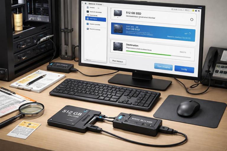
You have removed a 512 GB SSD from a Windows laptop and connected it to your workstation using a SATA-to-USB adapter and a hardware write blocker. You need a full physical image for later analysis.
Execution in FTK Imager
- Create Disk Image > Physical Drive > select the 512 GB SSD by model and size.
- Image Type: choose E01 to support segmentation and metadata.
- Metadata: enter case and evidence identifiers and note the adapter/write blocker used.
- Destination: choose your acquisition SSD, folder
CASE123\EVID04\ACQ\images\. - Segmentation: set 2 GB or 4 GB segments if you anticipate transferring the image later.
- Verification: enable verification to detect acquisition issues early.
- Start: monitor for read errors; if none, allow completion.
- Post-check: add the image back into FTK Imager and confirm partitions appear (EFI/System, OS, Recovery) and that the OS volume shows expected directories.
Practical Example: Targeted Collection from a Live System (Limited Scope)
Scenario
You are authorized to collect only a specific project directory and a set of application logs from a workstation, and you must do so quickly without taking the machine offline.
Execution in FTK Imager
- Add Evidence Item: add the logical drive or the specific folder path that contains the project directory.
- Navigate: locate the project folder and required log locations.
- Select and collect: create a container of selected items with a clear name indicating it is a targeted collection.
- Record paths: ensure the report/log reflects the original paths so an examiner can interpret context later.
- Verify: open the resulting container and confirm key files open in preview (for example, a few representative documents and log files).
Common Pitfalls and How to Avoid Them in FTK Imager Workflows
Imaging the wrong disk
This is one of the most damaging mistakes. Reduce risk by disconnecting unrelated drives, confirming model/serial where possible, and cross-checking capacity and partition layout in the preview before acquisition.
Writing the image to the source or to an unreliable destination
Always confirm the destination path is on a separate, stable drive. Avoid writing images to network shares unless your environment is designed for it and you have tested throughput and reliability. A dropped network connection can interrupt long acquisitions.
Forgetting segmentation when needed
If the destination file system has size limits, a single-file image may fail mid-way. Decide segmentation up front based on destination constraints and transfer plans.
Not checking the image opens after acquisition
A quick post-acquisition open in FTK Imager can catch missing segments, permission issues, or incomplete writes before you return the source device to storage. Make it a standard step: open the image, expand the tree, and preview a few files.