What “Smart Receptacles” and “Appliance Control Integration” Mean in the Field
In a smart home, receptacles and appliance feeds stop being “dumb endpoints” and become controllable, measurable, and automatable loads. Integration typically falls into three categories:
- Smart receptacles (in-wall): A duplex receptacle that looks like a standard device but includes internal switching and often metering. Some models switch one half (split control) and leave the other always-on; others switch both. Control may be via Wi‑Fi, Zigbee, Z‑Wave, Thread/Matter, or a proprietary hub.
- Smart plug-in modules: A plug-in adapter (smart plug) that provides on/off control and sometimes energy monitoring. These are common for lamps and small appliances and are often used when in-wall replacement is not desired.
- Dedicated appliance control: Hardwired control for specific appliances (water heater, recirculation pump, disposal, dishwasher, under-sink booster, towel warmer, etc.) using contactors, appliance-rated relays, or manufacturer integration. This category also includes “smart outlets” that are actually part of an appliance circuit strategy (e.g., a controlled receptacle for a freezer with monitoring and alerts).
From an electrician’s perspective, the integration work is less about “adding an app” and more about ensuring the device is correctly applied to the load type, installed to code, protected appropriately (GFCI/AFCI where required), and commissioned so it behaves predictably during outages, network loss, or hub failure.
Use Cases That Drive Device Choice
Controlled convenience loads
Typical examples: holiday lighting, floor lamps, coffee station accessories, towel warmer, dehumidifier (with constraints), or a recirculation pump on a schedule. These loads are usually within 15 A/20 A branch-circuit limits and are good candidates for smart receptacles or smart plugs.
Monitoring and alerts
Energy monitoring can detect abnormal patterns: a sump pump that runs too long, a freezer that stops cycling, or a server rack that draws more than expected. Some smart receptacles provide per-outlet metering; smart plugs often provide whole-device metering. The integration goal is to expose that data to the home automation system and configure notifications.
Load shedding and demand management
Some projects require shedding noncritical loads during peak demand or generator operation. Controlled receptacles can be assigned to “nonessential” groups (e.g., garage beverage fridge, decorative loads). For larger loads, use dedicated appliance control (contactor/relay) rather than switching through a receptacle device not rated for the duty.
- Listen to the audio with the screen off.
- Earn a certificate upon completion.
- Over 5000 courses for you to explore!

Download the app
Safety and compliance-driven control
Examples: disabling a receptacle at night in a child’s room, controlling a workshop receptacle bank, or ensuring a garbage disposal cannot be energized unintentionally. These are valid, but they must be implemented without defeating required protections (GFCI/AFCI) and without creating a hazardous “unexpected energization” scenario for someone servicing equipment.
Device Selection: What to Verify Before You Buy or Install
Load type and duty cycle
Many smart receptacles and smart plugs are intended for general-purpose resistive loads. Motor loads (compressors, pumps, some fans) can have high inrush current. Heating appliances can run near the device’s continuous rating for long periods. Verify:
- Amperage rating: 15 A vs 20 A devices; do not install a 15 A receptacle on a 20 A circuit where a 20 A receptacle is required by code (e.g., single receptacle on a 20 A circuit).
- Horsepower/motor rating: If controlling a motor load, confirm the device is explicitly rated for motor loads or has an HP rating.
- Continuous load behavior: If a load can run for 3 hours or more, treat it as continuous in your planning and ensure the device’s thermal performance is acceptable.
- Inrush tolerance: Refrigerators/freezers and some pumps can trip or weld contacts if the device is not designed for the inrush.
Control method and ecosystem compatibility
Integration success depends on how the device communicates:
- Wi‑Fi: Simple deployment, but depends on router coverage and can be chatty on crowded networks.
- Zigbee/Z‑Wave: Mesh networks with a hub; often stable for in-wall devices, but ensure the hub supports the specific device and features (metering, per-outlet control).
- Thread/Matter: Increasingly common; verify whether the controller (hub) supports Matter and whether the device exposes the needed clusters/features (on/off, energy reporting).
Also verify whether the device supports local control (continues to operate with the LAN/hub) versus cloud-only control. For critical loads (freezer monitoring, sump pump alerts), prefer local-first behavior and robust offline states.
GFCI/AFCI and location rules
Smart receptacles must still comply with required protections. Key checks:
- GFCI: Kitchens, bathrooms, garages, outdoors, basements, laundry areas, and other locations as required. If the smart receptacle is not itself GFCI, it must be protected by an upstream GFCI device or breaker where permitted.
- AFCI: Many dwelling unit circuits require AFCI protection. Smart receptacles generally do not replace AFCI requirements; coordinate with breaker selection.
- Weather resistance: Outdoor locations require WR receptacles and appropriate in-use covers. Many “smart receptacles” are not WR; use listed outdoor smart solutions or protect with appropriate enclosures.
- Tamper resistance: TR requirements still apply in dwelling units. Confirm the smart receptacle is TR where required.
Physical constraints: box fill, depth, heat
Smart receptacles are often deeper than standard devices. Verify box depth and conductor count. Overcrowded boxes lead to heat buildup and nuisance failures. If replacing an existing receptacle in a shallow box, plan for a deeper box or a different approach (smart plug module, or relocate control upstream with an appliance-rated relay if appropriate).
Wiring Patterns You’ll See (and How Smart Receptacles Change Them)
Standard feed-through receptacle
Most receptacles are wired as feed-through: line in and line out on the same device. With a smart receptacle, confirm whether the device supports feed-through and whether it switches only the receptacle or also affects downstream loads. Some smart receptacles are designed to control only their own outlets; others may not be intended as a pass-through for downstream receptacles. Always follow the manufacturer’s line/load labeling.
Split receptacle (half-switched) conversions
In some homes, a receptacle has one half controlled by a wall switch. If replacing that receptacle with a smart receptacle, you must confirm whether the smart device supports split control. Many do not. If split control is required, alternatives include:
- Use a smart receptacle model specifically designed for split (top/bottom) control.
- Convert the circuit to always-hot at the receptacle and use a smart plug for the controlled load (if acceptable).
- Move control to the switch location using a smart switch/relay (only if it doesn’t repeat previously covered multi-way/neutral topics; focus here on receptacle behavior and device capabilities).
Multiwire branch circuits (MWBC) considerations
Where receptacles are on an MWBC, ensure the smart receptacle is compatible with the wiring method and that handle ties/common trip requirements are met at the breaker. Pay attention to shared neutrals and how the device senses line/neutral. If the device’s electronics are sensitive to shared neutral conditions or requires a dedicated neutral reference, choose a different device or reconfigure per code and manufacturer guidance.
Practical Step-by-Step: Replacing a Standard Receptacle with a Smart Receptacle
This procedure assumes you are installing a listed smart receptacle in a standard indoor location and that required upstream protections (GFCI/AFCI) are already addressed. Always follow local code and manufacturer instructions.
1) Pre-checks and planning at the device location
- Identify the circuit and confirm breaker size (15 A vs 20 A).
- Confirm the receptacle type required (TR, WR, GFCI-protected, etc.).
- Check box depth and conductor count; plan for pigtails if needed to reduce device terminal crowding.
- Determine whether the receptacle is feed-through to other outlets (multiple cables in the box).
- Determine whether it is split-switched (tab removed, switched leg present).
2) De-energize and verify
- Turn off the breaker.
- Verify de-energized at the receptacle with an appropriate tester.
- Confirm the circuit is not backfed (e.g., shared neutrals or miswired multi-circuit conditions).
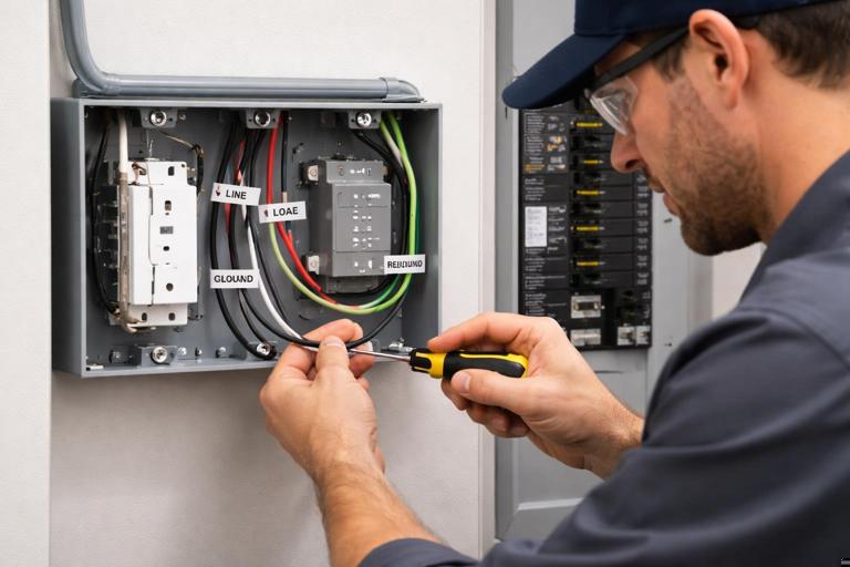
3) Document existing conductors
Before disconnecting, take a clear photo and note:
- Which conductor is line hot (incoming feed).
- Which conductor(s) are load hot (outgoing feed to downstream receptacles).
- Neutral bundle arrangement.
- Ground connection method.
Smart receptacles often have distinct LINE and LOAD terminals/leads. Misplacing these can cause the device to appear dead, fail to control correctly, or create unsafe conditions.
4) Prepare connections (pigtails recommended)
When there are multiple conductors in the box, use pigtails so the smart receptacle is not used as the splice point for multiple downstream conductors (unless the device is specifically listed for that termination method). A typical approach:
- Splice incoming hot + outgoing hot(s) + a hot pigtail.
- Splice neutrals + a neutral pigtail (if the device requires neutral termination).
- Splice grounds + a ground pigtail to the device yoke/ground terminal.
// Conceptual only (not a substitute for code/manufacturer instructions) Hot feed in ─┬─ Hot out to downstream ├─ Hot pigtail to smart receptacle LINE Neutral in ─┬─ Neutral out ├─ Neutral pigtail to smart receptacle (if required) Ground in ─┬─ Ground out ├─ Ground pigtail to device5) Terminate on the smart receptacle
- Connect hot pigtail to the device’s LINE hot terminal/lead.
- Connect neutral pigtail to the device’s neutral terminal/lead (if applicable).
- If the device supports and requires a LOAD terminal for downstream controlled feed, connect per instructions; otherwise keep downstream feed always-hot via splice and only control the receptacle itself.
- Connect equipment ground to the device ground.
6) Mount, restore power, and verify basic operation
- Carefully fold conductors to avoid pinching and to maintain device clearance.
- Install the receptacle and cover plate.
- Restore power and test with a plug-in tester and a known load.
- Verify that downstream receptacles (if any) are energized as expected.
7) Commissioning: pairing and naming
Commissioning is where many installations fail. Do it methodically:
- Put the device into pairing mode as instructed.
- Add it to the correct home/hub and assign it to the correct room.
- Name it by function and location (e.g., “Kitchen Coffee Station Outlet” rather than “Outlet 7”).
- If the device supports it, set the power-on state after outage (restore last state vs always on vs always off). Choose based on safety and client expectations.
- Enable energy reporting if needed and confirm the hub/app actually displays it.
Practical Step-by-Step: Integrating Appliance Control Without Abusing a Smart Plug
Some appliances should not be controlled by a general-purpose smart plug or receptacle due to inrush, duty cycle, or safety implications. When you need smart control but the load is not suitable for a receptacle device, use an appliance-rated control method.
Example: controlling a 240 V water heater via a contactor (control integration concept)
Instead of switching the heater directly with a small smart device, you use a properly rated contactor and let a smart controller switch the contactor coil (or use a purpose-built water heater controller). The smart system then schedules or sheds the heater without overstressing electronics.
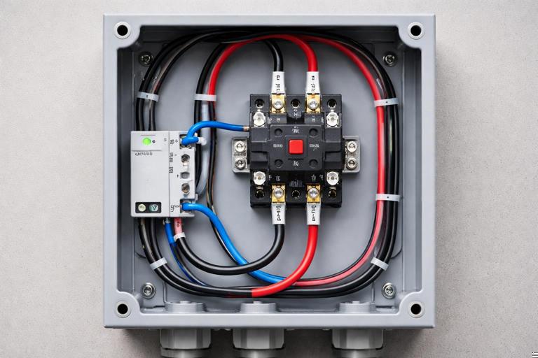
- Select a contactor with appropriate voltage and current rating for the heater load.
- Provide an enclosure and wiring method per code.
- Use a smart relay/controller that is listed for the control circuit and compatible with the automation ecosystem.
- Implement a manual override/disconnect strategy appropriate for servicing.
This pattern generalizes to other high-demand loads: baseboard heaters, large pumps, EVSE enable/disable inputs (when supported by manufacturer), or any load where the switching device must be robust and listed for the application.
Energy Monitoring: Turning Measurements into Useful Automation
When a receptacle or plug provides power data, integration is more than “seeing watts.” Practical uses include:
- State inference: If a washing machine draws < 5 W for 10 minutes, mark cycle complete and send a notification.
- Fault detection: If a freezer normally cycles between 80–140 W and suddenly stays at 0 W during expected run times, alert the homeowner.
- Standby reduction: If an entertainment center draws 25 W overnight, schedule off during sleeping hours, but ensure devices that need updates remain powered.
When configuring thresholds, measure real behavior first. Many appliances have variable-speed drives and non-intuitive power signatures. Avoid hair-trigger alerts by using time delays and hysteresis (e.g., “below 10 W for 15 minutes”).
Common Integration Pitfalls (and How to Avoid Them)
Using a smart plug on a load that should not be switched
Examples: refrigerators/freezers (risk of spoilage), medical equipment, aquariums, sump pumps, or anything where unintended off-state is hazardous. If monitoring is desired, consider a monitoring-only device or configure automation rules that never turn the device off, only alert.
GFCI interactions and nuisance trips
Some smart devices have internal EMI filters that can contribute to leakage current. If installed downstream of a GFCI, nuisance trips may occur. Mitigations include:
- Use devices known to be compatible with GFCI protection.
- Reduce the number of filtered devices on a single GFCI where practical.
- Verify wiring integrity and neutral/ground separation; leakage-like symptoms can be caused by wiring faults.
Box crowding and thermal issues
Smart receptacles dissipate heat. Overfilled boxes, back-to-back devices in insulated walls, or high continuous loads can lead to early failure. Choose deeper boxes, use pigtails to reduce stress, and avoid placing high-draw continuous loads on devices not designed for it.
Unexpected behavior after power loss
Clients often care most about what happens after an outage. Decide and document:
- Should the receptacle return to ON (e.g., freezer), OFF (e.g., space heater), or last state (e.g., lamp)?
- Should schedules resume immediately or wait for time sync?
- Is local control available if internet is down?
Downstream load confusion (line/load mis-termination)
Miswiring line and load can cause partial operation: the receptacle may power but not switch, or downstream receptacles may be unintentionally controlled. Always identify feed vs onward conductors and follow device labeling.
Troubleshooting Smart Receptacles and Controlled Appliance Loads
Symptom: receptacle has no power after installation
- Verify breaker on and no upstream GFCI tripped.
- Confirm line/load not reversed (if device has distinct terminals).
- Check neutral continuity and splice integrity (loose neutral is common).
- Confirm the device is not in a “disabled” state due to internal protection or configuration.
Symptom: receptacle powers but will not pair or frequently drops offline
- Check signal strength at the box location (Wi‑Fi RSSI, Zigbee/Z‑Wave mesh quality).
- Confirm the device is on the correct frequency/region (especially Z‑Wave).
- Look for metal boxes, dense tile backsplashes, or appliances that attenuate RF; consider adding mesh repeaters or relocating the hub.
- Update firmware if supported and stable; avoid updating during critical occupancy periods.
Symptom: controlled appliance behaves erratically (cycles, chatters, or won’t start)
- Suspect inrush/current rating mismatch; verify device suitability for motor/compressor loads.
- Check for voltage drop under load; smart devices may be more sensitive to low voltage.
- For contactor-based control, verify coil voltage, wiring, and that the smart controller output is rated for the coil current.
Symptom: nuisance tripping (breaker, GFCI, or AFCI)
- Confirm correct wiring and no shared neutral issues.
- Temporarily remove the smart device and test with a standard receptacle to isolate whether the device contributes to the trip.
- Check the load for faults (heaters, pumps, and outdoor equipment are common culprits).
- Consider a different listed device model known to be compatible with the protection type.
Commissioning Checklist for a Professional Handover
- Device labeled in the panel schedule and in the app/hub with matching names.
- Power-on behavior after outage set and tested.
- Automation rules documented (what turns it on/off, schedules, and overrides).
- Critical loads identified and protected from accidental shutoff (permissions, lockouts, or “monitor-only” rules).
- Client shown manual control method (local button, app, voice, or hub) and what happens if internet is down.
- Energy monitoring calibrated: baseline readings captured and alert thresholds set with time delays.