What “planning for connected loads” means in a smart home
Smart home electrical system planning for connected loads is the process of designing circuits, enclosures, wiring pathways, and control interfaces so that “smart” devices (loads with communications, sensors, or automation logic) operate safely, reliably, and serviceably. A connected load is not only a device that consumes power; it also participates in control and monitoring through a protocol (wired or wireless), has standby power behavior, may require continuous power for electronics, and can introduce new failure modes (firmware lockups, network dropouts, nuisance tripping due to leakage, inrush, or harmonics).
In practical terms, planning means answering these questions before rough-in and panel work: Which loads will be controlled, how (switching vs dimming vs variable speed), from where (local, app, automation), what happens during network outages, what power quality and grounding requirements exist, and how the system will be expanded and serviced later. The goal is to avoid common field problems such as smart switches that need neutrals but were installed in switch loops, dimmers that flicker due to incompatible drivers, overloaded multi-gang boxes, Wi‑Fi dead zones that cause “random” device failures, and panels that cannot accommodate future smart breakers or energy monitoring.
Inventory and classify connected loads
Step 1: Build a room-by-room load schedule that includes “smart attributes”
Start with a conventional load schedule, then add smart-specific columns. For each room/area, list every controlled load and note: voltage, wattage/VA, driver type (LED driver, electronic transformer, motor drive), control method (on/off, phase-cut dimming, 0–10 V, DALI, relay contactor, VFD), whether the device needs unswitched power, and whether it must operate during internet/network outages.
- Lighting loads: recessed LED, tape lighting, chandeliers, exterior fixtures, landscape lighting transformers.
- Motor loads: bath fans, range hoods, ceiling fans, blinds/shades, garage door openers, pumps.
- HVAC-related loads: thermostats, air handlers, humidifiers, ERV/HRV, mini-split controls, boiler controls.
- Receptacle-connected “smart” loads: smart plugs, EVSE, appliances with Wi‑Fi, entertainment racks.
- Safety and security: alarm panels, cameras, NVR, access control, smoke/CO interconnect modules (where permitted), water leak shutoff valves.
- Infrastructure loads: network switches, routers, wireless access points, hubs/bridges, PoE injectors, structured wiring panels.
Step 2: Identify control-critical vs convenience loads
Classify each connected load as control-critical (must work locally and predictably) or convenience (nice-to-have automation). Control-critical examples: stair lighting, exterior egress lighting, bathroom fan timers, sump pump monitoring, boiler enable, smoke/CO requirements. Convenience examples: accent lighting scenes, holiday outlets, voice-controlled lamps.
This classification drives decisions such as whether to use a hardwired control bus, whether to provide manual override, and whether to place devices on UPS-backed circuits.
- Listen to the audio with the screen off.
- Earn a certificate upon completion.
- Over 5000 courses for you to explore!

Download the app
Choose the control architecture early
Distributed control vs centralized control
Distributed control places smart switches/dimmers at the point of use, controlling line voltage directly. It often reduces panel complexity and keeps wiring conventional, but requires correct box fill, neutral availability, and careful device compatibility with the load.
Centralized control places relays/dimmers in a panel or enclosure (lighting control panel, DIN rail cabinet), and uses low-voltage keypads or control stations in rooms. It can simplify multi-way control and reduce device count in wall boxes, but increases planning requirements for homeruns, enclosure space, heat dissipation, and service access.
Many projects use a hybrid: centralized for large lighting groups and exterior loads, distributed for single fixtures and retrofit areas.
Wired vs wireless considerations (planning impact)
Wireless devices can be excellent, but planning must account for coverage, interference, and power requirements. Wired control (low-voltage bus, Ethernet/PoE, or dedicated control cable) typically improves determinism and reduces troubleshooting time, but requires pathways and terminations.
From an electrical planning standpoint, the key is to avoid designing a system that only works when the network is perfect. For control-critical loads, ensure there is a local control path (physical switch, keypad, or maintained contact) that functions even if the hub is down.
Circuit design for connected loads
Neutral strategy and switch box requirements
Many smart switches and dimmers require a neutral to power their electronics. Planning should assume neutrals are needed at most switch locations unless a specific device is confirmed to operate without one and the load type is compatible. Avoid relying on legacy switch loops that omit neutrals in the box.
Practical approach: standardize on bringing line, load, neutral, and ground to each switch box where feasible. This reduces device constraints and simplifies future upgrades.
Dedicated circuits and “always-on” power
Connected loads often need continuous power for communications and monitoring. Decide which outlets or equipment must remain energized and label them accordingly. Examples include: network rack receptacles, hubs/bridges, alarm panel transformer receptacle, sump pump monitoring, and refrigerator circuits (even if not “smart,” they may be monitored).
When a load must be controlled but its electronics need constant power (e.g., smart bulbs), plan the control method: either keep the circuit unswitched and use a compatible smart controller, or use a smart switch configured to send commands without cutting power (where allowed by the system design). This must be coordinated with the homeowner’s expectations: a wall switch that “does nothing” electrically can confuse occupants unless clearly specified and labeled during commissioning.
Inrush current and nuisance tripping
LED drivers, electronic transformers, and motor loads can have high inrush current. Smart relays and breakers may be more sensitive to inrush or leakage depending on design. Planning steps include: grouping similar loads, avoiding excessive driver count on one dimmer channel, and selecting control devices rated for the load type (including inrush rating, not just steady-state watts).
For example, a bank of LED downlights on one dimmer may be within wattage limits but still flicker or trip due to driver compatibility and inrush. Plan to split large lighting groups into multiple channels, especially for long runs or mixed fixture types.
GFCI/AFCI interactions with connected devices
Some connected loads (especially those with EMI filters or power supplies) can contribute to leakage current. When multiple such devices share a GFCI-protected circuit, nuisance tripping can occur. Planning should consider: limiting the number of electronic power supplies per protected circuit, using dedicated circuits for problem loads, and ensuring neutrals are not shared improperly across devices protected by different GFCI/AFCI devices.
Also plan physical access: if a smart device is downstream of a GFCI receptacle, a trip can make the device appear “offline.” For critical devices, consider locating protection devices where they can be reset easily and where status can be observed.
Lighting control planning: compatibility and wiring choices
Match dimming method to driver type
Lighting is the most common connected load category and the most common source of callbacks. Planning must align the control method with the fixture driver:
- Phase-cut (forward/reverse) dimming: common for line-voltage dimmers; requires compatible LED drivers. Reverse-phase often performs better with electronic drivers but must be confirmed.
- 0–10 V dimming: requires a separate low-voltage control pair plus line voltage; good for many commercial-style fixtures and can be more stable for large groups.
- Digital protocols (e.g., DALI): require dedicated bus wiring and compatible drivers; strong for large, addressable systems.
Planning step: for each lighting group, document the fixture model/driver and the intended control device model. If fixtures are not selected yet, specify “driver must be compatible with [control method]” in the electrical notes and coordinate with the lighting designer or supplier.
Multi-way and scene control
Connected loads often require multi-way control (3-way/4-way) and scenes. Decide whether multi-way will be handled by travelers (traditional wiring) or by smart companion devices/keypads. This affects rough-in: traditional travelers require additional conductors between boxes; smart companion approaches may reduce traveler needs but may require neutrals and specific device placement.
Practical planning rule: if the control system is not finalized, rough-in travelers and neutrals so you can support either approach later. The incremental wire cost is often far less than the cost of opening walls later.
Panel, enclosure, and space planning
Serviceability and expansion
Connected load systems evolve. Plan for spare breaker spaces, enclosure room for add-on modules, and physical cable management. If using centralized lighting control, allocate wall space for the control panel with clear working clearance and ventilation. If using DIN rail components, plan a cabinet with room for wire duct, terminal blocks, and labeling.
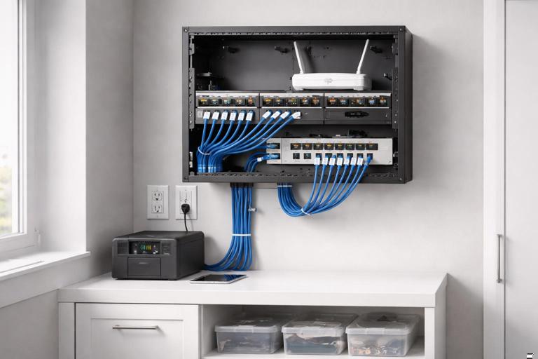
Include a structured wiring area for network gear and smart home hubs. Even if the electrician is not installing IT equipment, the electrical plan should provide: dedicated receptacles, optional UPS receptacle location, and pathways for Ethernet to access points and key devices.
Heat and derating in multi-gang boxes
Smart dimmers and relays can run warmer than mechanical switches, and multi-gang installations may require derating. Plan box sizes and device grouping to avoid overheating and nuisance shutdown. Use deeper boxes where possible and avoid packing multiple high-load dimmers in a tight multi-gang without considering manufacturer derating charts.
Power quality and grounding considerations for electronics-heavy homes
Connected loads introduce many switch-mode power supplies and electronic drivers. Planning should consider power quality issues that show up as flicker, audio noise, or device resets. Practical measures include: separating sensitive AV/network circuits from high-noise loads where feasible, providing dedicated circuits for home office and network racks, and ensuring grounding and bonding are executed cleanly with proper terminations.
Where surge protection is part of the scope, plan locations for whole-panel protection and point-of-use protection for sensitive equipment. Even when surge devices are installed later, leaving space and a clear path in the panel makes the work cleaner.
Network and low-voltage coordination that affects electrical planning
Plan power for network infrastructure
Even though Ethernet and PoE are low-voltage, the electrical system must support the network that makes connected loads “connected.” Provide dedicated receptacles for modem/router, switches, and wireless access points (if not PoE). Consider placing critical network equipment on a UPS-backed receptacle or circuit so that controls remain available during brief outages.
For PoE cameras and access points, coordinate cable pathways and equipment locations early. The electrical plan should avoid placing line-voltage conductors in a way that complicates low-voltage routing and should reserve space for conduits or raceways where required by the project’s standards.
Wireless coverage impacts device placement
Wireless smart devices can fail due to poor signal, which is often misdiagnosed as an electrical issue. Planning can reduce this by coordinating access point locations and ensuring they have power and backhaul. For example, ceiling-mounted access points typically need a cable path and either PoE from a switch or a nearby receptacle for an injector. If the electrician provides the receptacle, place it where it will not be switched off inadvertently.
Resilience planning: what happens when parts fail
Local control and fallback behavior
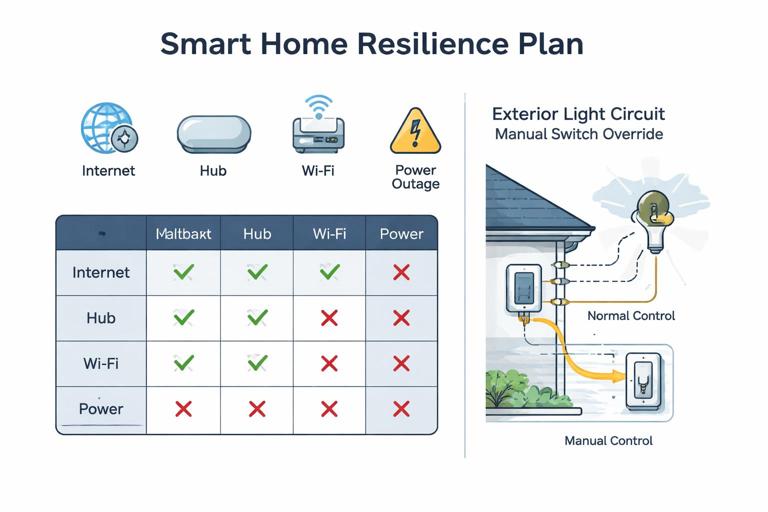
Define the expected behavior during failures: internet down, hub down, Wi‑Fi down, power outage, or a single device failure. For control-critical loads, ensure local manual control remains functional. This may mean using smart switches that still switch locally without cloud access, or using hardwired keypads to a local controller rather than cloud-only logic.
Planning step: write a “fallback matrix” for key loads. Example entries: “Exterior entry lights: local switch works always; automation adds dusk-to-dawn; if controller offline, lights still operate manually.” This matrix helps prevent designs where a homeowner cannot turn on a light because a server is down.
UPS and generator interfaces
If the home has a generator or battery backup, identify which connected loads and infrastructure must be on backed-up power: network rack, controller, select lighting, garage door opener, security system. Coordinate transfer equipment and ensure that any smart load controllers are compatible with the power source (some electronics are sensitive to waveform quality on certain generators).
Practical step-by-step planning workflow
Step-by-step: from concept to rough-in
1) Interview and use-case capture. Document what the occupants want to control and how they expect it to behave. Capture scenes (e.g., “Goodnight,” “Away,” “Movie”), schedules, and any accessibility needs (large buttons, voice control, motion automation). Identify any non-negotiables like “wall switches must always work.”
2) Create the connected load schedule. Build the room-by-room list with smart attributes: load type, control method, neutral requirement, inrush concerns, and criticality. Flag unknown fixture models as “TBD” and note required dimming method.
3) Select the control architecture per area. Decide distributed vs centralized per floor/zone. For example: centralized for main floor lighting scenes and exterior, distributed for bedrooms and retrofit spaces. Document where controllers, relay panels, and hubs will live.
4) Draft circuiting with separation and dedicated runs. Allocate dedicated circuits for network/AV rack, mechanical equipment, and any loads known to cause nuisance trips. Group lighting circuits by function and location, but avoid mixing incompatible driver types on one dimmer channel.
5) Plan switch box wiring standards. Standardize conductor sets to switch boxes (line/load/neutral/ground) and decide how multi-way will be handled. If uncertain, rough-in travelers and neutrals to preserve options.
6) Size boxes and enclosures for electronics. Choose deeper boxes for smart devices, plan multi-gang spacing, and account for derating. For centralized panels, allocate cabinet space, ventilation, and service clearance.
7) Coordinate low-voltage and network power. Ensure receptacles for network gear, PoE switch locations, and access point power needs are addressed. Reserve pathways and avoid conflicts with line-voltage routing.
8) Produce labeling and documentation requirements. Plan a labeling scheme for circuits, controlled loads, and always-on receptacles. Include a schedule that maps each smart control channel to the physical load and location.
Examples that translate planning into field decisions
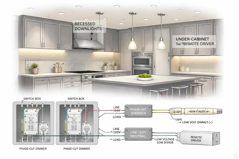
Example 1: Kitchen lighting with mixed fixture types
A kitchen has recessed LEDs, under-cabinet tape, and pendants. Planning identifies that the tape lighting uses a remote driver that is not compatible with phase-cut dimming. Solution: put recessed LEDs and pendants on a phase-cut smart dimmer channel (after confirming compatibility), and put tape lighting on a separate 0–10 V or dedicated driver/controller channel. Provide neutrals in all switch boxes and split circuits so that a single driver issue does not take down all kitchen lighting.
Example 2: Exterior lighting that must work during network outages
Exterior entry and pathway lights are control-critical. Planning sets them on a conventional switching path with a smart switch that performs local control without cloud dependency. Automation adds dusk-to-dawn via local controller logic. The circuit is labeled clearly in the panel, and the switch location is chosen for intuitive manual operation.
Example 3: Network rack and smart controller reliability
A home uses multiple connected loads that depend on a local hub. Planning provides a dedicated 20 A circuit to the rack location, a duplex receptacle with one outlet fed by a UPS, and a clear note that the receptacle must be unswitched. The rack circuit is kept separate from garage and exterior receptacles to reduce nuisance trips. This prevents “whole house is offline” complaints caused by a tripped garage GFCI.
Example 4: Bathroom fan with humidity automation
A bathroom fan is a motor load with a desire for humidity-based automation. Planning chooses a control method rated for motor loads and ensures the fan can be overridden manually. If the fan includes an electronic module that requires constant power, the plan avoids switching the neutral and ensures the control device is compatible with the fan’s electronics.
Documentation deliverables that prevent callbacks
Connected load schedule (minimum fields)
- Area/room
- Load description and fixture/device model (or TBD with requirements)
- Supply voltage and estimated load (W/VA/HP)
- Control type (relay, dimmer type, 0–10 V, etc.)
- Criticality (control-critical vs convenience)
- Neutral required at control location (yes/no)
- Notes on inrush/compatibility
- Circuit number and panel location
Control map and labeling plan
Create a map that ties each control channel (switch, relay, dimmer output) to the physical load. In centralized systems, this is essential: “Relay 3 = Dining chandelier,” “Dimmer 2 = Kitchen downlights.” In distributed systems, it still helps with troubleshooting: “Kitchen 3-gang left device controls under-cabinet.”
Label always-on receptacles and critical equipment circuits. If the project includes homeowner handoff documentation, include a simple “what to check first” list (e.g., which breaker feeds the hub, where the UPS is, which GFCI protects exterior outlets) without turning it into a closing section.
Commissioning considerations that should be planned during design
Even though commissioning happens later, planning should anticipate it. Provide access to fixtures and drivers, avoid burying junctions behind fixed millwork, and ensure there is a way to isolate and test circuits. Plan for temporary power needs during programming and for safe access to panels and enclosures.
Where firmware updates or device pairing is expected, ensure that devices are installed in locations where they can be reset or serviced without special equipment. For example, placing a smart relay above a hard lid ceiling with no access panel creates long-term service risk.