What Changes in Circuit Design When Loads Become “Smart”
Smart devices often look like small loads, but they introduce design constraints that are easy to miss: continuous standby draw, inrush currents from electronic power supplies, sensitivity to voltage drop and neutral integrity, and the need to keep “always-on” devices powered even when occupants want local control. Circuit design for smart homes is less about adding more circuits blindly and more about grouping loads intentionally, providing clean power and reliable neutrals, and organizing the panel so troubleshooting and future expansion are straightforward.
Typical smart-home electrical loads include smart switches/dimmers, smart receptacles, smart lighting drivers, motorized shades, smart appliances, EVSE, heat-pump equipment, network/PoE power supplies, security panels, and controllers. Many of these rely on electronics that can misbehave with shared neutrals, loose terminations, or excessive voltage drop. Your design goal is to deliver stable power, limit nuisance tripping, and make it obvious in the panel what feeds what.
Key design principles
- Separate “critical always-on” from “user-controlled” circuits: controllers, network gear, security, and automation hubs should not be on circuits that occupants routinely switch off.
- Group by function and failure impact: lighting, receptacles, HVAC controls, and IT/low-voltage power supplies often deserve different circuits.
- Plan for electronics behavior: switching power supplies can create inrush and leakage; dimmers can be sensitive to load type; AFCI/GFCI selection matters.
- Design for serviceability: clear circuit naming, logical breaker layout, and spare capacity reduce time on callbacks.
Load Calculations: Translating Smart Loads into Real Panel Demand
Load calculations determine whether the service and panel can support the connected loads and how to distribute circuits. Smart devices add many small loads, but the big drivers remain HVAC, cooking, EV charging, water heating, and general-use receptacles/lighting. The “smart” aspect affects how you estimate continuous loads, diversity, and future expansion.
Step-by-step: build a practical load list
Start with a worksheet that captures both nameplate and expected operating characteristics.
- List fixed appliances and equipment: range, dryer, dishwasher, disposal, microwave, water heater, HVAC outdoor/indoor units, sump pump, well pump, etc.
- List dedicated smart loads: EVSE, smart spa/pool equipment, smart irrigation pump, server rack/UPS, PoE switches/injectors, security power supplies.
- Estimate general lighting and receptacle load: include smart lighting drivers and smart receptacles as part of general load unless dedicated.
- Identify continuous loads: anything expected to run for 3 hours or more (network gear, some lighting, ventilation, certain pumps, EVSE during long sessions).
- Note special characteristics: motor starting, electronic inrush, sensitive electronics, and whether the load is 120 V or 240 V.
For each item, capture: voltage, amperage or watts, whether continuous, and whether it needs a dedicated circuit. If you only have watts, convert to amps using I = W/V. If you have VA for power supplies, use VA rather than watts for conservative sizing.
- Listen to the audio with the screen off.
- Earn a certificate upon completion.
- Over 5000 courses for you to explore!

Download the app
Continuous load treatment (practical sizing rule)
When a load is continuous, size the circuit so the continuous portion does not exceed 80% of the breaker rating (equivalently, multiply continuous load by 125% for sizing). This matters for smart-home “infrastructure” loads that are always on.
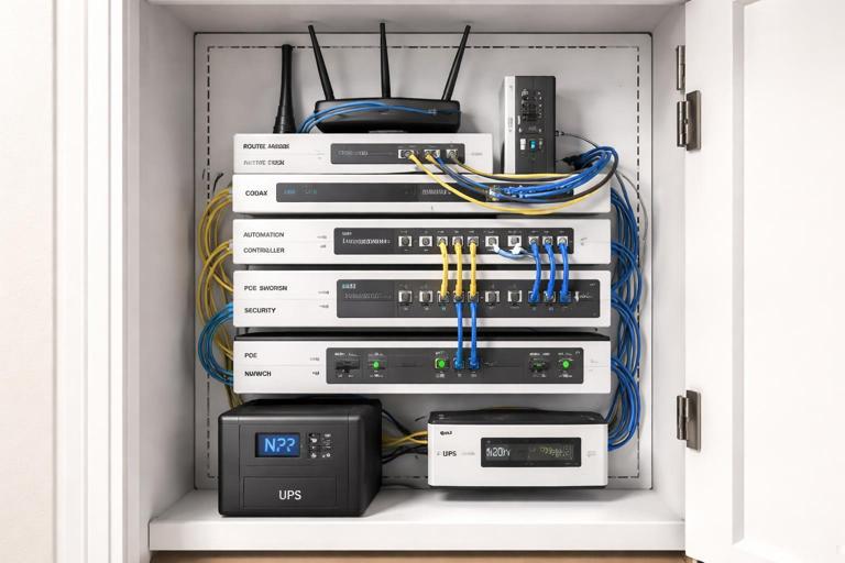
Example: a structured media cabinet has a router (20 W), modem (15 W), controller (10 W), PoE switch (150 W), and NVR (60 W). Total is 255 W. At 120 V, that is about 2.1 A. Even with 125% sizing, it remains small, but the key is not the ampacity; it is the reliability and the decision to keep it on a dedicated or clearly identified circuit, possibly backed by a UPS.
Inrush and electronic power supplies
Many smart devices use switching power supplies. Individually they are small, but in aggregate they can cause nuisance trips on certain protective devices, especially when many drivers energize simultaneously after an outage. LED drivers and plug-in transformers can have high inrush for milliseconds. Practical mitigation is usually circuit distribution rather than oversizing breakers: spread large groups of LED drivers across multiple circuits and avoid putting all smart lighting power supplies on one breaker if the home has extensive low-voltage lighting.
Demand and diversity: practical approach for smart homes
Even when code methods allow demand factors, smart homes often have higher simultaneous usage because automation can coordinate loads (e.g., “goodnight” scenes turning on pathway lights, HVAC setbacks, and charging schedules). When you design, consider realistic peak scenarios:
- Morning peak: kitchen appliances + lighting + HVAC + water heating.
- Evening peak: cooking + entertainment + lighting scenes + EV charging start time.
- Outage recovery: many electronic loads re-energize at once.
For a practical field approach, treat large discretionary loads (EVSE, spa, electric heat) as the primary service drivers, then ensure the remaining general load has comfortable headroom. If the service is near capacity, consider load management strategies (listed energy management systems, EVSE with load-shedding, or controlled circuits), but keep the wiring and panel organization ready for those additions.
Branch Circuit Design for Smart Devices
Dedicated circuits vs shared circuits
Smart devices fall into three broad categories for circuiting decisions:
- Infrastructure loads (recommended dedicated or clearly segregated): network rack, security panel power supply, automation controller, PoE switch, Wi‑Fi access point power supplies, and any equipment that must remain on.
- High-load smart appliances (dedicated by nature): EVSE, smart dryer/range, heat pump, smart water heater, pool equipment.
- Distributed smart controls (shared with the loads they control): smart switches/dimmers, smart receptacles, smart lighting drivers, smart exhaust fans.
As a rule, if turning off a breaker would disable the home’s ability to control or monitor safety-related functions, that circuit should be labeled and kept separate from convenience loads. For example, avoid feeding the internet modem from a general bedroom receptacle circuit that occupants might overload with a space heater.
Neutral requirements and multi-wire branch circuits (MWBC)
Many smart switches require a neutral at the switch box. If you are designing new circuits or rewiring, plan neutrals in every switch location where smart controls may be installed. This reduces the temptation to use “no-neutral” devices that may have compatibility issues with certain LED loads.
MWBCs can be efficient, but they demand correct handle ties/common trip where required, correct phasing, and excellent termination practices. Smart electronics can be more sensitive to neutral problems; a loose shared neutral can create unpredictable behavior and equipment damage. If MWBCs are used, keep them well-documented and avoid mixing neutrals between circuits.
Voltage drop and “clean power” considerations
Smart devices may reset or drop offline with modest voltage sag. Long runs feeding clusters of electronics (media rooms, offices, smart lighting power supplies) should be checked for voltage drop under expected load. Practical steps:
- Keep long-run circuits lightly loaded or upsize conductors when appropriate.
- Place high-inrush loads (vacuum outlets, garage tools) on separate circuits from sensitive electronics.
- For controllers/network gear, consider a dedicated receptacle circuit located near the structured wiring panel, optionally with surge protection and UPS.
AFCI/GFCI coordination and nuisance trips
Modern dwellings often require AFCI and/or GFCI protection in many areas. Smart devices can introduce leakage current (especially power supplies and filters) that accumulates when many devices share a GFCI device. Practical design choices include:
- Distribute electronic loads across multiple protected circuits rather than concentrating them.
- Use the correct type of protective device for the location and load (for example, avoid mixing large numbers of plug-in power supplies on a single GFCI receptacle if it becomes nuisance-prone).
- Keep neutrals isolated per circuit and avoid shared neutral mistakes, which can cause immediate tripping.
Panel Organization: Making Smart Homes Serviceable
Panel organization is not cosmetic; it is a troubleshooting tool. Smart homes add many circuits and sub-systems, and future electricians (or you on a callback) need to identify circuits quickly. A well-organized panel reduces downtime when a homeowner reports “the smart lights are offline” or “the hub keeps rebooting.”
Breaker layout strategy
Organize breakers in a way that matches how the home is used and how you will diagnose problems. One practical approach is to group by system:
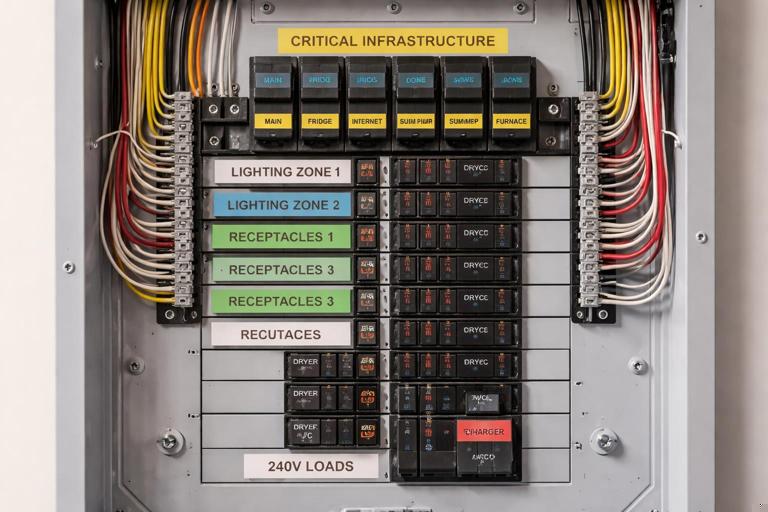
- Critical infrastructure: network/IT receptacle circuit, security panel transformer circuit, automation controller circuit, garage door opener circuit (if critical for access), sump pump (if applicable).
- Lighting: separate lighting circuits by floor/zone; keep smart lighting power supplies grouped but not all on one breaker.
- General receptacles: by area, with special attention to office/media spaces.
- Kitchen/laundry/bath: as required, with clear labeling for countertop small-appliance circuits and dedicated appliance circuits.
- Mechanical: HVAC air handler, condenser/heat pump, boiler controls, ventilation, etc.
- Large discretionary loads: EVSE, spa, sauna, workshop subpanel.
Within each group, keep a consistent left-to-right or top-to-bottom pattern. If the panel supports it, reserve a block of spaces for future smart expansions (additional lighting drivers, exterior cameras, landscape lighting transformer, etc.).
Labeling: go beyond “Lights” and “Plugs”
Smart devices make generic labels inadequate. Use labels that identify both the area and the function. Examples:
- “IT/Network Rack Receptacles (UPS)”
- “Lighting – Main Floor – Smart Switches/Downlights”
- “Exterior – Cameras/PoE Power Supply”
- “Garage – EVSE 48A”
- “Kitchen – Countertop SA #1 (GFCI/AFCI)”
When a circuit feeds a smart lighting driver or control panel, include the enclosure location: “LED Driver – Basement Mech Room Panel A.” This saves time when locating hidden power supplies.
Directory accuracy and as-built documentation
Smart homes change: devices are added, circuits are repurposed, and homeowners plug in new equipment. Build a habit of producing an as-built circuit directory that is easy to update. Practical steps:
- Use a printed directory with enough space for notes.
- Include subpanel references: “Subpanel B in garage feeds…”
- Record breaker type (AFCI/GFCI/dual-function) if it matters for troubleshooting.
- For critical circuits, note “Do not turn off” and what will be affected.
Practical Step-by-Step: Designing Circuits and Panel Layout for a Smart-Heavy Home
Step 1: Identify “always-on” and “mission-critical” loads
Create a short list of loads that should remain powered for the smart home to function safely and predictably:
- Internet modem/router, Wi‑Fi access points
- Automation hub/controller
- Security/alarm panel and cameras (or their power supplies)
- Sump pump or critical drainage equipment (where applicable)
- Medical equipment receptacles (if specified)
Decide whether these will be on one dedicated “Smart Home Infrastructure” circuit or split into two circuits for redundancy (for example, one for network gear and one for security/cameras). If a single breaker trip would take down everything, consider separating.
Step 2: Map smart lighting and control topology to circuits
Smart lighting can be line-voltage switched loads, centralized lighting panels, or a mix. Regardless of topology, you must map which loads share a breaker and what happens if it trips.
- Keep egress and safety lighting from being entirely on one circuit.
- Distribute exterior lighting so one trip does not black out all perimeter lighting.
- For large LED driver installations, distribute drivers across multiple circuits to reduce inrush concentration.
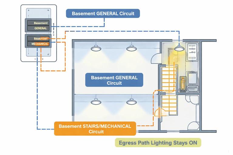
Practical example: Instead of one “Basement lights” circuit feeding all recessed fixtures and stair lights, split into “Basement general” and “Basement stairs/mechanical.” If the general circuit trips, the stair path remains lit.
Step 3: Allocate receptacle circuits with smart usage in mind
Home offices, media rooms, and structured wiring locations often have higher continuous electronic loads than traditional bedrooms. Allocate circuits accordingly:
- Provide a dedicated circuit for a home office if it will host PCs, monitors, printers, and UPS.
- Keep AV racks on a dedicated circuit to reduce interference from vacuum cleaners or treadmills on the same circuit.
- For garages, separate door openers and network extenders from tool receptacles if heavy tools are expected.
Step 4: Size and place circuits for large smart loads (EVSE as a model)
EV charging is a common smart load with long continuous run times. Treat it as a continuous load for circuit sizing. Choose conductor size, breaker rating, and receptacle vs hardwired connection per equipment instructions and local requirements. Also consider where the EVSE will be located and whether future upgrades (higher current, second EVSE) are likely.
Panel organization tip: place EVSE breakers near other large 240 V loads and label with the EVSE maximum output (e.g., “EVSE 40A output / 50A breaker”). This helps future changes and load management discussions.
Step 5: Check panel capacity and physical space
Smart homes often need more breaker spaces than older homes due to added dedicated circuits and protective device requirements. Confirm:
- Service ampacity is adequate for calculated load and expected future additions.
- Panel has enough spaces for current circuits plus spares.
- Breaker types required (AFCI/GFCI/dual-function) are available and compatible with the panel.
If space is tight, consider a subpanel strategy: for example, a dedicated “low-load electronics and lighting” subpanel near the structured wiring area, or a garage subpanel for EVSE and workshop loads. The goal is not just capacity, but logical separation and shorter branch runs.
Step 6: Create a circuit schedule that matches the home’s zones
Before pulling wire, draft a circuit schedule that includes breaker number, area, load type, and notes. Example structure:
1-2  HVAC Air Handler (240V)  Notes: Disconnect in attic mech space
3    IT/Network Rack Recepts  Notes: UPS, surge protection
4    Security/Camera PSU      Notes: Do not switch off
5    Lighting Main Floor A    Notes: Kitchen + hall
6    Lighting Main Floor B    Notes: Living + dining
7    Office Recepts           Notes: Dedicated
8    Media Room AV Rack       Notes: Dedicated
...
This schedule becomes the basis for panel labeling and commissioning tests.
Troubleshooting-Oriented Design Choices (Designing to Avoid Future Callbacks)
Keep smart controls powered when loads are off
Some smart control schemes require constant power to the control device even when the controlled load is off. Ensure the wiring method supports this. For example, smart switches need line and neutral in the box; smart relays in junction boxes need accessible enclosures and proper fill calculations. If a homeowner expects “manual off” at a wall switch, avoid designs where a switch cuts power to the smart controller upstream unless that behavior is intentional and documented.
Minimize hidden power supplies without access
Smart lighting often introduces drivers and transformers. Place them where they can be serviced and where their feeding breaker is clearly labeled. Avoid burying drivers above inaccessible ceilings. If drivers must be remote, document their location and the circuit feeding them.
Plan for surge protection and sensitive electronics
Smart homes have more electronics exposed to surges. While surge protection selection and installation details may be handled elsewhere, your circuit design should anticipate it: provide space for protective devices, keep neutrals and grounds properly terminated, and avoid long shared paths that can increase impedance during surge events.
Balance loads across legs (practical panel performance)
Even with many small smart loads, balancing 120 V circuits across both legs helps reduce neutral loading and improves overall performance. When you group circuits by area, still check that the total estimated load per leg is reasonably balanced, especially when adding large 120 V continuous loads like network racks or extensive lighting drivers.
Worked Example: Circuit and Panel Organization for a Smart-Device-Heavy Remodel
Scenario: A remodel adds extensive smart lighting, a structured wiring cabinet with PoE cameras, a home office, and an EVSE. The home has a modern panel with limited spare spaces.
1) Load identification
- EVSE: continuous high load (dedicated 240 V circuit).
- PoE cameras + NVR + PoE switch: continuous electronics load (dedicated 120 V circuit recommended).
- Smart lighting: multiple zones with LED drivers (distribute across two or more lighting circuits).
- Home office: higher continuous receptacle load (dedicated 120 V circuit recommended).
2) Circuit allocation
- One 2-pole breaker for EVSE.
- One 1-pole breaker for IT/Network rack receptacles (with UPS).
- One 1-pole breaker for security/camera power supplies (or combine with IT if small, but label clearly).
- Two 1-pole breakers for main-floor lighting zones (split by area and egress needs).
- One 1-pole breaker for office receptacles.
3) Panel organization
Place the IT/security circuits at the top of the panel (easy to find, “do not turn off”), followed by lighting zones, then receptacles, with the EVSE near other 240 V loads. Reserve at least two spare spaces for future additions like landscape lighting transformer or a second PoE switch.
4) Documentation
Update the directory with device locations: “IT/Network Rack Recepts – Closet 2F,” “Camera PSU – Basement utility room,” and note any GFCI/AFCI requirements. This prevents a common service call where someone shuts off “closet plugs” and accidentally kills the network.
Field Checklist: Before You Finalize the Design
- Are neutrals present in all switch boxes where smart controls may be installed?
- Are critical smart-home infrastructure loads on a clearly labeled, stable circuit?
- Have you distributed LED drivers and electronic power supplies to reduce inrush concentration?
- Are long runs checked for voltage drop where sensitive electronics are used?
- Is the panel layout logical, balanced, and leaving spare capacity?
- Is the circuit directory specific enough to locate drivers, controllers, and power supplies quickly?