What You Are Really Selecting: Control Method + Electrical Interface + Load Compatibility
When you choose a smart switch, dimmer, relay, or in-wall module, you are not just choosing a brand or an app ecosystem. You are selecting (1) how the device controls power (mechanical switching, electronic switching, phase-cut dimming, 0–10 V control, dry-contact control), (2) how it is powered and wired in the box (line/neutral requirements, grounding, traveler arrangements, low-voltage terminals), and (3) what kinds of loads it can safely and reliably control (incandescent, LED drivers, magnetic/electronic transformers, motors, contactors, smart bulbs, etc.). Most field problems come from mismatching one of those three layers.
A practical selection workflow is: identify the load type and its control input, confirm the required control behavior (on/off vs dimming vs speed vs scene), then pick the device whose electrical interface matches the wiring available and whose ratings and compatibility list match the load. Only after that do you decide on features like multi-way support, scene control, or local/remote operation.
Device Types and What They Actually Do
Smart switches (on/off)
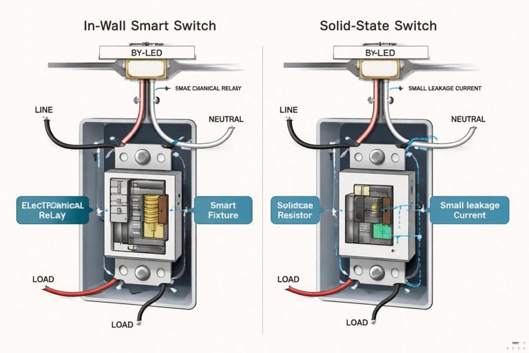
A smart switch is typically an in-wall device that switches the line conductor to the load (or sometimes switches a control input). Internally it may use a relay (electromechanical) or a solid-state device (triac/MOSFET/SSR). Relay-based switches tend to be more forgiving with unusual loads and have true off-state isolation, while solid-state designs can leak a small current and may require a bypass in some LED applications.
Smart dimmers (phase-cut)
Most residential smart dimmers are phase-cut dimmers. They modulate AC power by cutting part of each sine wave. Two common types:
Leading-edge (forward-phase): typically triac-based; historically used for incandescent and many magnetic transformers. Can be noisy with some LED drivers.
Continue in our app.- Listen to the audio with the screen off.
- Earn a certificate upon completion.
- Over 5000 courses for you to explore!

Download the app
Trailing-edge (reverse-phase): often MOSFET-based; generally smoother with many dimmable LED drivers and electronic transformers, often quieter.
Phase-cut dimming is not the same as “dimming” a smart bulb. Smart bulbs usually want constant power and are dimmed digitally; putting them on a dimmer often causes flicker, dropouts, or damage.
Smart relays / in-wall modules
Smart relays are compact modules installed in a box, fixture canopy, or panel enclosure (where permitted). They can provide one or more channels of on/off control and sometimes energy monitoring. They are useful when you want to keep an existing mechanical switch, add smart control behind it, or control loads from a location without room for a full smart switch.
Relays can be:
Dry-contact (potential-free): the relay contacts are isolated and can switch a separate circuit or a control input (e.g., boiler thermostat input, garage door opener input, contactor coil circuit). This is often the safest way to interface with equipment that should not be fed line voltage from the smart device.
Line-voltage switching: the module switches the same line voltage that powers it.
0–10 V dimmers and controllers
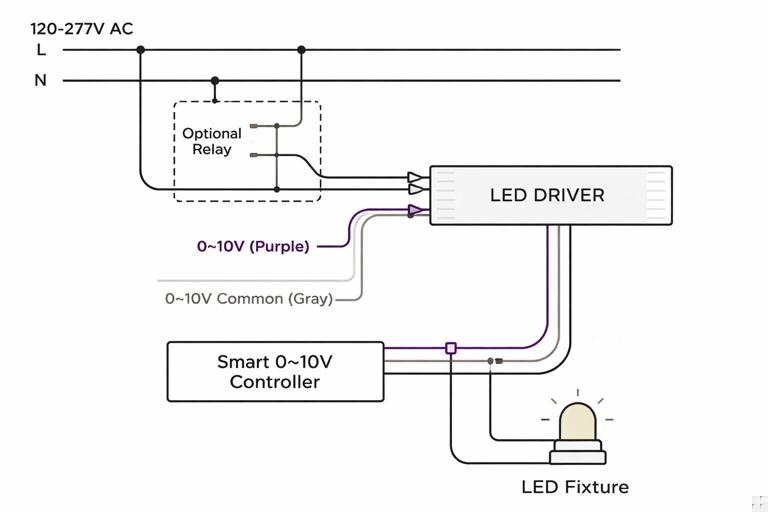
Many commercial-style LED drivers and some residential recessed fixtures use 0–10 V control. In these systems, the line voltage powers the driver continuously, and a separate low-voltage pair (purple/gray in many conventions) carries the dimming signal. A “0–10 V smart dimmer” is usually a controller that provides the 0–10 V signal and may also include a relay to switch line power. Selection must consider whether the driver expects sourcing or sinking control (most are sinking) and whether you need power switching in addition to dimming.
Fan controls and motor loads
Fan controls are not interchangeable with light dimmers. Motor loads have inrush and inductive characteristics that can overheat a dimmer or cause humming. Use a device rated for fan/motor control (often multi-speed or specific to ceiling fans) or use a relay to switch a fan controller designed for the motor type.
Key Electrical Requirements to Verify Before You Buy
Neutral requirement and powering method
Many smart switches and dimmers require a neutral in the box to power their electronics. Some “no-neutral” devices steal a small current through the load; these are more prone to issues with low-wattage LED loads (ghosting, flicker, failure to turn fully off) and may require a bypass/resistor at the fixture. Selection rule: if a neutral is present, prefer a neutral-required device for best compatibility and fewer callbacks.
Grounding and box fill
Smart devices are often deeper than standard switches and generate some heat. Confirm the box has adequate volume for conductors and device depth, and that grounding is continuous. Overcrowding increases heat and can push devices beyond their derating limits.
Single-pole, 3-way, 4-way, and multi-location control
Multi-way arrangements vary by manufacturer:
Smart master + dumb travelers: the smart device replaces one switch and uses standard travelers with a mechanical companion switch. Compatibility depends on wiring topology (line at switch vs line at light) and device design.
Smart master + smart accessory: a proprietary companion device communicates with the master (wired or wireless). This can improve dimming performance and reduce miswiring risk but locks you into a system.
Wireless multi-way: one device controls the load; other wall controls are battery or line-powered remotes. Great for retrofit when travelers are missing or wiring is nonstandard.
Selection rule: identify where line and load actually are, and whether travelers exist and are usable. Do not assume a “3-way capable” device works in every 3-way wiring scenario.
Derating and thermal limits
Dimmers and some smart switches must be derated when installed in multi-gang boxes or when multiple devices are side-by-side. The faceplate and yoke can be part of the heat dissipation path. If you ignore derating, you may see thermal shutdown, shortened life, or nuisance flicker. Always check the manufacturer’s derating chart and compare it to the actual installation (number of gangs, ambient temperature, enclosure type).
Inrush current and electronic drivers
LED drivers and electronic transformers can have high inrush current even when the steady-state wattage is low. A device rated “600 W incandescent” may only be rated “150 W LED” or may have a maximum number of drivers. Selection should be based on the device’s LED rating and, when available, its inrush specification (peak current, microseconds/milliseconds). If the manufacturer provides a compatibility list for specific lamp/driver models, treat it as a primary selection tool.
Load Types and Compatibility Rules
Incandescent and halogen (resistive)
These are the easiest loads. Most dimmers work well, and minimum load issues are rare. Still, observe maximum wattage and derating. For relay switches, incandescent inrush can be high; ensure the relay rating covers tungsten loads if specified separately.
Dimmable LED lamps on phase-cut dimmers
LED retrofits vary widely. Two common failure modes are flicker (visible modulation) and dropout (lamp turns off at low dim levels). Selection steps:
Confirm the lamp is labeled “dimmable” and ideally lists compatible dimmer types.
Choose a dimmer with an LED-specific rating and, if possible, adjustable low-end trim.
Prefer trailing-edge dimmers for many LED lamps, especially where flicker/noise is a concern.
Check minimum load. Some dimmers need a minimum wattage to maintain stable control; if the load is too small (e.g., one 7 W lamp), you may need a bypass or a different dimmer.
LED fixtures with dedicated drivers
Integrated LED fixtures may use internal drivers that support phase-cut dimming, 0–10 V, DALI, or proprietary controls. Do not assume “dimmable” means phase-cut. Read the fixture/driver spec sheet for the dimming method and choose the matching controller:
Phase-cut driver: use a compatible phase-cut dimmer (often trailing-edge preferred).
0–10 V driver: use a 0–10 V controller; do not use a phase-cut dimmer on the line side unless the driver explicitly supports it.
Non-dimmable driver: use an on/off switch or relay only.
Magnetic vs electronic low-voltage transformers
Low-voltage lighting can be powered by magnetic (inductive) or electronic (capacitive/high-frequency) transformers. Compatibility matters:
Magnetic transformers: often prefer leading-edge dimmers rated for MLV (magnetic low voltage). These dimmers handle inductive loads and may include a larger heat sink.
Electronic transformers: often prefer trailing-edge dimmers rated for ELV (electronic low voltage). Using the wrong type can cause buzzing, overheating, or poor dimming range.
Selection rule: identify transformer type from labeling or model number; do not guess based on fixture appearance.
Motors, pumps, and inductive loads
For inductive loads, look for ratings in HP (horsepower) or motor load ratings, not just watts. Many smart switches are not rated for motor loads even if the wattage seems low. For pumps, disposals, and fans, use a motor-rated switch/relay or control a contactor/relay designed for the motor circuit. If the equipment has its own controller (HVAC air handler, variable-speed pump), you often want to switch a control input (dry contact) rather than switching the power feed.
Heaters and high-current resistive loads
Baseboard heaters and radiant heat circuits often exceed typical smart switch ratings and may require line-voltage thermostats or contactors. If smart control is desired, use a smart thermostat or a relay/contactor arrangement rated for the load and duty cycle. Selection must consider continuous load behavior and enclosure heat.
Smart bulbs and smart fixtures
Smart bulbs generally require constant power. The correct “switch” for a smart bulb is often a smart on/off switch configured for smart-bulb mode (no local load switching) or a scene controller that sends commands without cutting power. If you must provide a wall control, choose a device that can disable the internal relay (or use a dedicated remote) so the bulb stays powered.
Step-by-Step Selection Process (Field Workflow)
Step 1: Identify the load and its control method
Write down: load type (lamp/fixture/driver/motor), quantity, and how it is intended to be controlled (on/off, dimming, speed, scenes). For lighting, determine whether dimming is phase-cut or 0–10 V by checking the driver/fixture documentation or labeling.
Step 2: Confirm wiring constraints at the box
Open the box (safely) and verify: presence of neutral, number of conductors, grounding, available box volume, and whether it is a multi-way location. Note whether line and load are in the same box. This determines whether you can use a standard smart switch/dimmer, need a no-neutral model, or should use an in-wall relay at the fixture instead.
Step 3: Choose device category and switching technology
Match the device to the job:
On/off lighting with mixed lamp types: relay-based smart switch is often the safest.
Dimming LED retrofits: LED-rated dimmer with trim adjustments; consider trailing-edge.
Driver-based fixtures with 0–10 V: 0–10 V controller (and decide if you also need a line relay).
Equipment control inputs: dry-contact relay module.
Motor loads: motor-rated control or contactor interface.
Step 4: Verify ratings using the right metric
Do not rely on “max watts” alone. Check:
LED wattage rating (often much lower than incandescent rating).
ELV/MLV rating if transformers are involved.
Motor/HP rating for inductive loads.
Inrush limits or maximum number of drivers/lamps.
Derating for multi-gang installations.
Step 5: Check compatibility lists and known-good pairings
Many dimmer manufacturers publish tested lamp lists. Use them. If the exact lamp/driver is not listed, choose a dimmer known to perform well with similar driver types and ensure it has low-end trim and (ideally) selectable leading/trailing edge modes.
Step 6: Plan for commissioning adjustments
For dimmers, plan to set:
Minimum dim level (to prevent dropout/flicker).
Maximum level (to reduce buzz or overdrive on some lamps).
Dimming curve (linear vs logarithmic, if available).
Fade rates (for perceived smoothness).
For relays controlling contactors or drivers, plan for whether you need default-on behavior after power loss and whether the device supports it.
Practical Examples (Selection Scenarios)
Example 1: Retrofit LED lamps on an existing dimmer circuit
Scenario: A dining room chandelier is converted from incandescent to eight dimmable LED lamps. The customer wants smooth dimming without flicker.
Load: eight dimmable LED lamps (phase-cut compatible).
Wiring: neutral present in the box.
Selection: a neutral-required LED-rated smart dimmer, preferably trailing-edge or selectable mode.
Commissioning: set low-end trim so lamps do not drop out at 5–10%, set max to reduce any audible buzz.
Common mistake avoided: choosing a no-neutral dimmer that leaks current and causes ghosting when the chandelier is “off.”
Example 2: Under-cabinet lighting with an electronic transformer
Scenario: Under-cabinet tape lighting is fed by an electronic transformer/driver that supports ELV reverse-phase dimming.
Load: electronic transformer (ELV), LED tape.
Selection: an ELV-rated smart dimmer (trailing-edge) with sufficient ELV wattage rating and derating allowance.
Verification: confirm the transformer’s minimum load and dimming method; ensure the dimmer’s minimum load is met or plan a bypass if required.
Common mistake avoided: installing an MLV/leading-edge dimmer that causes transformer buzz and unstable dimming.
Example 3: Bathroom exhaust fan control
Scenario: Customer wants the exhaust fan on a smart control with schedules and manual override.
Load: motor load (fan).
Selection: a smart on/off switch explicitly rated for motor loads or a relay module with motor rating; avoid a light dimmer.
Extra: if the fan has a humidity-sensing controller, consider leaving power constant and using the controller’s input (if available) rather than switching power.
Example 4: Controlling a boiler or garage door input
Scenario: The goal is to trigger a boiler call-for-heat input or a garage door opener button input.
Load: low-voltage control circuit; must not be fed line voltage.
Selection: a dry-contact smart relay module (potential-free contacts).
Wiring: connect the relay contacts in parallel with the existing button/thermostat contacts; power the module separately as required.
Common mistake avoided: using a line-voltage smart switch and accidentally applying 120/230 V to a low-voltage input.
Step-by-Step: Selecting and Setting Up a Smart Dimmer for LED Loads
1) Confirm the lamps/fixtures are dimmable and identify dimming type
Check packaging/spec sheet for “dimmable” and whether it references leading-edge, trailing-edge, ELV, or specific dimmer families. If the fixture uses a driver, confirm it supports phase-cut dimming (not only 0–10 V).
2) Add up the actual LED wattage and compare to the dimmer’s LED rating
Example: 10 lamps × 9 W = 90 W. If the dimmer is rated 150 W LED in single-gang but derates to 100 W in a 2-gang, you are close to the limit; choose a higher-rated model or separate the load.
3) Choose a dimmer with adjustment features
Look for: low-end trim, selectable phase mode (if available), and a published compatibility list. These features matter more than maximum wattage in many LED retrofits.
4) Install with attention to neutrals, grounds, and line/load identification
Follow the device diagram exactly. Many smart dimmers are sensitive to line/load reversal and will behave erratically if miswired. Ensure grounds are properly terminated and that the box is not overfilled.
5) Commission: set minimum level and test across the range
With the customer’s preferred lamps installed, dim slowly from 100% down to the lowest setting. If flicker or dropout occurs, raise the minimum trim until stable. If buzzing occurs at high levels, reduce the maximum slightly or change phase mode if supported.
Step-by-Step: Selecting a Smart Relay Module Behind an Existing Switch
1) Decide whether you need line switching or dry contact
If you are switching a lighting load directly, line switching is typical. If you are interfacing with a control input, choose dry contact.
2) Verify space, heat, and conductor management
Relay modules add bulk. Confirm the box has enough volume and that the module will not be compressed against conductors. If the load is near the relay’s limit, consider a module with higher rating or move switching to a more suitable enclosure where permitted.
3) Determine switch input type
Some modules accept a momentary switch, some a maintained toggle, and some can be configured for either. Match the module to the existing wall control or plan to replace the switch.
4) Confirm load rating and inrush tolerance
For LED drivers, look for relay ratings that mention LED or electronic loads, not only resistive. If the driver count is high, consider using the smart relay to drive a contactor with appropriate ratings.
Trouble Patterns That Point to a Selection Problem (Not an Installation Problem)
Flicker at low dim levels
Often indicates an LED driver/lamp that is not compatible with the dimmer’s phase method or a minimum load issue. Solution is typically a different dimmer type (trailing-edge), trim adjustment, or a bypass.
Glow/ghosting when “off”
Common with no-neutral devices or solid-state switches that leak current. Fix by using a neutral-required device, adding a bypass at the load, or switching to a relay-based device with better off-state isolation.
Device overheats or shuts down
Usually derating/box fill/ambient temperature or load type mismatch (ELV/MLV, motor load on a non-motor-rated device). Fix by selecting a higher-rated device, reducing load, improving box conditions, or using a contactor/driver interface.
Buzzing from fixtures or dimmer
Often a phase-cut mismatch with transformer/driver type or operating near the edge of the dimming range. Fix by selecting ELV/MLV-correct dimmer, changing phase mode, or limiting max/min levels.
Quick Reference: Selection Checklist
Load type identified (resistive/LED driver/transformer/motor/control input).
Correct control method chosen (on/off, phase-cut, 0–10 V, dry contact).
Neutral availability confirmed; prefer neutral-required devices when possible.
Ratings checked using the correct category (LED/ELV/MLV/HP/inrush), with derating applied.
Multi-way method confirmed (standard travelers, companion accessory, or wireless remote).
Commissioning features available (trim, phase mode, curves) for dimming applications.
Smart bulbs/fixtures handled correctly (constant power + scene control, not phase-cut).