Why Neutrals, Grounds, and Terminations Matter in Smart-Home Retrofits
Smart-home electrical integration often fails for reasons that have nothing to do with Wi‑Fi, apps, or device pairing. The most common field problems are basic wiring realities: whether a neutral is present in the box, whether grounding is continuous and correctly bonded, and whether line-voltage terminations are made in a way that is mechanically secure, electrically sound, and code-compliant. Smart switches, dimmers, occupancy sensors, in-wall relays, and smart fan controls can be more sensitive than traditional mechanical switches because they may require a neutral to power internal electronics, they may leak small currents through the load when no neutral is available, and they may include electronics that are intolerant of loose connections, shared neutrals, or misidentified conductors.
This chapter focuses on three practical areas: (1) neutral requirements and how to verify and provide neutrals safely, (2) grounding and bonding continuity as it relates to smart devices and metal boxes, and (3) safe line-voltage terminations, including splices, pigtails, torque, and box fill considerations. The goal is to help you avoid nuisance behavior (flicker, ghosting, random resets), prevent overheating and arcing faults, and ensure safe servicing for the next technician.
Neutral Requirements in Smart Switch Locations
What the Neutral Does (and Why Smart Devices Often Need It)
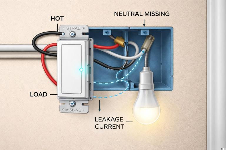
In typical 120 V branch circuits, the neutral is the grounded conductor that provides the return path for current. Traditional single-pole switches often interrupt only the ungrounded (hot) conductor and do not need a neutral in the switch box. Many smart controls, however, need continuous power for their radio, microcontroller, and sensing circuits. The simplest way to power those electronics is to connect line (hot) and neutral at the device, while the device switches the load using an internal relay or triac/MOSFET.
When a smart device is installed in a location without a neutral, some models attempt to power themselves by passing a small current through the load even when “off.” This can cause LED lamps to glow, flicker, or fail prematurely, and can cause the device to behave unpredictably with certain drivers or low-wattage loads. For this reason, identifying whether a neutral is present (and correctly part of the same circuit) is one of the first checks before selecting or installing a smart control.
Common Switch-Box Scenarios
Power to the light first (switch loop): Older wiring methods often bring line and neutral to the luminaire box, then send only a hot down to the switch and a switched hot back up. In this case, the switch box may have no neutral at all. You may see a 2-wire cable (plus ground) in the switch box with both conductors used as hot (one feed, one switched return). Modern code practices often require a neutral in most switch boxes, but existing homes can still have switch loops.
Continue in our app.- Listen to the audio with the screen off.
- Earn a certificate upon completion.
- Over 5000 courses for you to explore!

Download the app
Power to the switch box first: Line, neutral, and load conductors are present. This is the easiest case for smart switches because neutral is typically available as a splice bundle in the back of the box.
Multi-gang boxes with mixed circuits: A neutral bundle may be present, but it might not belong to the same circuit as the hot feeding the device location. Using a neutral from a different circuit can create objectionable current paths, nuisance tripping of GFCI/AFCI devices, and serious safety hazards.
3-way/4-way locations: Travelers and re-identified conductors can confuse identification. Some smart 3-way solutions require a neutral in at least one location; others require it in both. Always verify actual conductors present rather than assuming based on switch type.
How to Verify a Neutral in the Box (Field Procedure)
Use a methodical approach. Do not rely on conductor color alone, especially in older work or where re-identification is missing.
De-energize and verify: Turn off the correct breaker. Verify absence of voltage with a properly rated tester (non-contact as a preliminary check, then a two-pole tester or meter for confirmation). Confirm between hot-to-neutral and hot-to-ground reads 0 V after de-energizing.
Identify the feed hot: With power on briefly (if safe and permitted), identify which conductor is the constant hot using a two-pole tester to a known ground reference. De-energize again before manipulating conductors.
Locate the neutral splice bundle: In many boxes, neutrals are tied together with a wire connector and pushed to the back. A neutral bundle typically includes multiple white conductors. Confirm it is a true neutral by testing continuity to the neutral bar at the panel only if you can do so safely and without backfeeding; in practice, verifying that the neutral is part of the same cable set as the identified hot feed is often the safer field confirmation.
Confirm circuit pairing: Ensure the neutral you plan to use is in the same cable or raceway grouping as the hot feeding the device. If you have multiple circuits in the box, map which neutrals belong to which hots by cable tracing, labeling, or controlled isolation (one breaker on at a time) while maintaining safe practices.
Check for MWBC conditions: If you suspect a multi-wire branch circuit (shared neutral), confirm handle ties/common trip and correct phasing. Shared neutrals require careful attention to simultaneous disconnect and correct pairing to avoid overloading the neutral.
Practical tip: If you find a “neutral-looking” white conductor on a switch terminal, treat it as suspect. In switch loops, a white conductor may be used as an ungrounded conductor and should be re-identified (taped/marked) as hot. Never assume white equals neutral.
Providing a Neutral When None Exists
If the switch box has no neutral, you have a few options. The correct choice depends on access, construction, and the device requirements.
Run a new cable with neutral: Often the most robust solution is to replace the switch loop with a cable that includes a neutral (for example, replacing 2-wire with 3-wire plus ground where appropriate). This may involve fishing cable, opening walls, or using accessible attic/basement routes. Ensure conductor sizing, insulation rating, and routing comply with local code and the existing wiring method.
Relocate the smart control to a box that has neutral: In some designs, you can place an in-wall relay module at the luminaire box (where neutral is present) and use the existing switch leg as a low-current control input if the module supports it. This keeps line-voltage switching at a location with full conductors available.
Use a no-neutral-rated device (with caution): If permitted and compatible with the load, a no-neutral smart switch may work, but you must verify minimum load requirements, compatibility with LED drivers, and whether a bypass/load resistor is required at the fixture. Treat bypass components as heat-producing devices that must be installed per manufacturer instructions and in an approved enclosure/space.
Grounding and Bonding for Smart Controls
Ground vs Neutral: Functional Differences
The neutral is a current-carrying conductor during normal operation. The equipment grounding conductor (EGC) is not intended to carry current during normal operation; it provides a low-impedance fault path to facilitate rapid overcurrent device operation during a fault. Smart devices often include metal yokes, heat sinks, EMI filtering, and surge suppression components that reference ground for safety and noise control. A continuous, correctly bonded grounding system reduces shock hazard and can improve device stability in electrically noisy environments.
Bonding Metal Boxes and Device Yokes
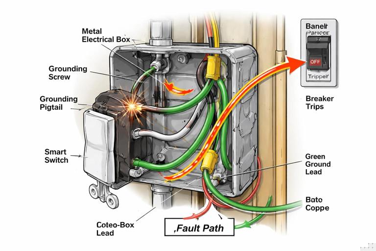
In metal boxes, bonding is critical. A metal box must be bonded to the EGC so that if a hot conductor contacts the box, the fault current has a low-impedance path back to the source, clearing the breaker quickly. Many smart switches have a green ground screw or ground lead that must be connected to the EGC. Do not rely on incidental contact between the device yoke and a painted box or a loose mounting screw for bonding.
Step-by-step: bonding in a metal box
Verify EGC presence: Confirm a bare/green EGC is present in the cable or raceway system. In older conduit systems, the metal raceway may serve as the EGC if continuous and properly connected; verify continuity and integrity.
Bond the box: Use an approved grounding screw or clip in the threaded grounding hole of the metal box. Attach a grounding pigtail to the box.
Bond all grounds together: Splice all EGCs with the box bonding pigtail and a device grounding pigtail (if the device does not have a self-grounding clip/yoke rated for the application). Use an approved connector sized for the number and gauge of conductors.
Connect device ground: Terminate the device ground lead/screw to the grounding splice via pigtail. Ensure the connection is tight and conductors are not nicked.
Note: In plastic boxes, you still must connect the device ground to the EGCs, but you do not bond the box itself. Maintain continuity of the grounding conductors through the box with an appropriate splice.
Grounding in Multi-Gang Boxes and Mixed Wiring Methods
Smart retrofits frequently occur in multi-gang boxes where several switches share space. The grounding conductors must remain continuous and correctly spliced even if you replace only one device. If the box contains both NM cable and metal conduit entries, ensure bonding is correct for each wiring method. Do not cut back grounding conductors too short; maintain enough length for service loops and secure terminations.
GFCI/AFCI Considerations Related to Neutral and Ground
Smart devices can expose pre-existing wiring issues that were previously unnoticed. If a device causes a GFCI to trip, common causes include neutral-to-ground contact downstream, shared neutrals between circuits, or incorrect neutral connections in the box. AFCI nuisance trips can occur with loose terminations, arcing at backstabs, or failing loads. The corrective action is not to defeat protection devices; it is to locate and correct wiring faults, confirm correct circuit pairing, and ensure terminations are solid.
Safe Line-Voltage Terminations: Mechanical and Electrical Best Practices
Why Termination Quality Matters More with Smart Devices
Smart switches and in-wall modules often have electronics that are sensitive to voltage drop, heat, and electrical noise. A marginal splice that “worked fine” with a mechanical switch can create enough resistance to cause heating, intermittent resets, or communication dropouts. Additionally, many smart devices have larger bodies, leaving less free space in the box; cramped conductors are more likely to be stressed, leading to loosening over time.
General Rules for Reliable Terminations
Use the correct connector type: Match wire connectors (twist-on, lever-style, crimp sleeves) to conductor material (copper vs aluminum), gauge, and count. If aluminum is present, use connectors listed for AL/CU and antioxidant compound as required.
Prefer pigtails over device feed-through: When multiple conductors need to remain continuous (line feed to other loads, neutral continuation), splice and pigtail to the device rather than landing multiple conductors under a single terminal unless the device is specifically listed for that.
Torque matters: Many modern devices specify terminal torque. Use a torque screwdriver when required. Under-torque can lead to heating; over-torque can damage terminals or shear conductors.
Avoid backstabs: Push-in backstab connections on receptacles/switches are a common failure point. Use side screws or pressure-plate clamps where available.
Maintain conductor integrity: Do not nick copper when stripping. Use the strip gauge on the device. If a conductor is nicked, cut back and re-strip.
Respect bend radius and strain: Fold conductors neatly. Avoid sharp bends at the terminal that can stress the copper and loosen over time.
Step-by-Step: Replacing a Switch with a Neutral-Required Smart Switch
This procedure assumes a standard single-pole location with line, load, neutral bundle, and ground present. Always follow manufacturer instructions and local code.
De-energize and verify: Turn off the breaker and verify absence of voltage at the switch conductors.
Document existing wiring: Take a clear photo of the existing connections. Identify line (hot feed), load (switched leg), and ground. If the old switch has two similar terminals, do not assume which is line vs load without testing.
Prepare pigtails: If the box has feed-through conductors (line continuing to other devices), create a line splice with a pigtail to the smart switch line terminal. Do the same for neutral: add a neutral pigtail from the neutral bundle to the device neutral lead/terminal. Add a ground pigtail if needed.
Make splices: Strip conductors to the connector specification. For twist-on connectors, pre-twist only if required by the connector instructions; for lever connectors, fully insert to the strip length. Tug-test each conductor individually.
Terminate at the device: Connect line, load, neutral, and ground to the correct terminals/leads. Tighten to specified torque if provided.
Dress conductors and mount: Fold splices to the back, keeping the device cavity clear. Avoid placing wire connectors directly behind the device where they can press on terminals. Mount the device without pinching insulation.
Re-energize and test: Restore power. Verify manual control, app control, and that the load turns fully off without flicker. If flicker occurs, verify neutral integrity, load compatibility, and whether a bypass is required.
Step-by-Step: Safe Splicing and Pigtailing in a Crowded Multi-Gang Box
Assess box fill and device depth: Before adding smart devices, evaluate whether the existing box has sufficient volume for the conductor count and the larger device bodies. If not, plan for a deeper box or extension ring where permitted.
Separate circuits: If multiple circuits are present, keep conductors grouped by circuit. Label if necessary. Do not intermingle neutrals or hots between circuits.
Use compact connectors: Lever-style connectors can reduce bulk and improve serviceability, but ensure they are listed for the conductor types and counts. Avoid oversized twist-on connectors that create a large mass behind the device.
Short, consistent pigtails: Use pigtails long enough to service (commonly 6 inches minimum in many jurisdictions), but avoid excessive length that creates congestion. Keep pigtails consistent and route them along the box sides.
Stagger splices: Place splices at different depths so they do not stack into a single bulge. This reduces pressure on device terminals and helps the device sit flush.
Final inspection: Confirm no bare copper is exposed outside connectors, no insulation is under screw terminals, and grounds are continuous and bonded where required.
Identifying and Handling Common Neutral and Grounding Problems
Open Neutral Symptoms and Checks
An open neutral can cause smart devices to reboot, behave erratically, or fail to power up. In some cases, loads may backfeed through electronics, producing misleading voltage readings on high-impedance meters.
Symptoms: device dead or intermittent, lights flicker when other loads operate, voltage readings that appear normal with no load but collapse under load.
Checks: verify neutral splice tightness, inspect for broken conductors at wirenuts, confirm neutral continuity through upstream boxes, and check for shared neutral issues in MWBCs.
Bootleg Neutral-to-Ground Bonds in Device Boxes
Sometimes a device “works” only because someone tied neutral to ground in a box to create a return path. This is unsafe and can energize metal parts under fault conditions or create parallel neutral paths on grounding conductors. Smart devices may expose this because they draw continuous current. If you find neutral and ground tied together outside the service disconnect location, correct it by restoring proper neutral continuity and removing the improper bond.
Misidentified Conductors in Switch Loops
In older switch loops, a white conductor may be used as a hot feed to the switch. If it is not re-identified, it can be mistaken for a neutral and incorrectly connected to a smart device neutral terminal, creating immediate faults or damage. When you encounter a white conductor on a switch terminal, treat it as an ungrounded conductor until proven otherwise, and re-identify it with tape/marker per local requirements.
Line-Voltage Termination Details That Prevent Heat and Arcing
Terminal Types: Screw, Clamp, and Leads
Side screw terminals: Form a proper hook (if required by the device), wrap clockwise so tightening draws the conductor in. Ensure the hook is fully under the screw head and insulation is not trapped.
Pressure-plate clamp terminals: Insert straight stripped conductor to the specified strip length. These are often more reliable than hooks and reduce conductor damage.
Pre-attached leads: Many smart devices use stranded leads. Splice stranded-to-solid with connectors listed for mixed conductor types. Ensure all strands are captured; no whiskers should protrude.
Aluminum Conductors and Mixed-Metal Terminations
Some older homes have aluminum branch-circuit conductors. Smart device retrofits in these homes require special care. Aluminum has different thermal expansion characteristics and oxidation behavior than copper, increasing the risk of loose connections and overheating if not terminated correctly.
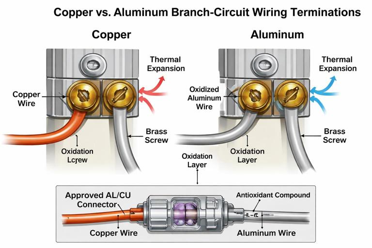
Use devices and connectors specifically listed for aluminum conductors (AL/CU) where applicable.
Use antioxidant compound if required by the connector/device instructions.
Do not land aluminum under terminals not rated for it.
Consider approved remediation methods (such as listed COPALUM or AlumiConn-style connectors) when transitioning to copper pigtails for device terminations.
Box Fill and Heat Management with Smart Devices
Smart dimmers and relays can generate more heat than mechanical switches, especially when controlling higher loads. Overcrowded boxes restrict airflow and can increase operating temperature, leading to derating requirements or premature failure. Ensure the box has adequate volume for conductor count and device size, and follow manufacturer derating charts for multi-gang installations where heat dissipation is reduced.
Practical workflow: Before installation day, open a representative box, count conductors, note box size/depth, and compare to the intended device dimensions. If the device is significantly deeper, plan for box replacement or extension rather than forcing the device into place.
Verification Tests After Termination
Electrical and Functional Checks
Continuity of ground: Verify the device yoke is bonded (especially in metal boxes). Use an appropriate tester to confirm low-impedance path where practical.
Correct line/load orientation: Some smart switches require line and load to be on specific terminals. If reversed, the device may power but not control correctly or may behave unpredictably.
Neutral integrity under load: If you suspect a weak neutral, test voltage with the load on and observe for drop or instability.
Thermal check: After operating at typical load for a period, feel for abnormal heat at the device faceplate area (without removing covers). If excessive, de-energize and re-check terminations, load level, and derating requirements.
Troubleshooting Patterns Specific to Neutral/Ground/Termination Issues
LED glow when off: often no-neutral device leakage current, incompatible driver, or missing bypass; also check for shared neutrals or induced voltage on travelers in 3-way runs.
Random device resets: loose line/neutral splice, backstab failure upstream, overloaded connector, or voltage sag from poor termination.
Breaker trips immediately: line-to-neutral short from miswired conductors, neutral tied to ground in a downstream box under GFCI protection, or incorrect connection in a multi-gang with mixed circuits.
AFCI trips when switching: arcing from loose terminal, damaged conductor, or failing load driver; re-terminate with proper torque and inspect conductor condition.
Reference Wiring Examples (Text-Based)
Example 1: Smart Switch with Neutral Present (Single-Pole)
Feed cable: Hot (black) ---------+------------------ to other loads (if any) Neutral (white) ------+------------------ to other loads (if any) Ground (bare/green) ---+------------------ to other grounds Splices in box: Hot splice: feed hot + onward hot + pigtail to smart switch LINE Neutral splice: feed neutral + onward neutral + pigtail to smart switch NEUTRAL Ground splice: all grounds + pigtail to box (metal) + pigtail to device Load cable: Load (black/red) ---------------------- to smart switch LOAD Neutral (white) -------------------- to neutral splice bundleExample 2: Switch Loop (No Neutral in Switch Box)
At light box: Feed hot (black) --------------------+---- to white down to switch (re-identified hot) Switched hot return (black) --------+---- from black up from switch to lamp hot Feed neutral (white) --------------------- to lamp neutral Ground continuous At switch box (2-wire + ground): White (re-identified hot) ---- on switch common (line feed) Black ------------------------- on switch other terminal (switched return) Ground ------------------------ to switch yokeIn this scenario, a neutral-required smart switch cannot be installed at the switch box without adding a neutral or relocating the smart control to a location where neutral is present.