Why retrofits are different in older homes
Retrofitting smart controls into older housing stock is less about adding “smart” features and more about working within physical and electrical constraints that were acceptable when the home was built. Common limitations include undersized boxes, brittle insulation, mixed wiring methods, missing equipment grounding conductors, shared neutrals, multi-wire branch circuits (MWBCs), legacy switching loops, and service equipment that has been modified over decades. The goal is to integrate modern controls without creating hidden failure points, overheating, unreliable operation, or code violations.
In retrofit work, the electrician’s advantage is process: verify what exists, identify constraints, choose the least invasive compliant method, and document what changed. A successful retrofit plan anticipates what you cannot change easily (finished plaster walls, inaccessible bays, historic trim) and uses strategies that minimize demolition while still delivering safe, maintainable results.
Typical legacy wiring constraints you will encounter
- No equipment grounding conductor (EGC): Two-wire NM, knob-and-tube remnants, or early BX/AC with questionable bonding.
- Small or shallow device boxes: Metal handy boxes, 1-gang plaster rings, or crowded multi-gang boxes with little free volume.
- Brittle insulation and heat-damaged conductors: Cloth/rubber insulation that cracks when moved.
- Mixed wiring methods: NM splices into conduit, old AC cable to NM transitions, or junctions buried behind finishes.
- Switch loops and nonstandard conductor use: White used as hot without re-identification, missing neutrals in switch boxes, travelers repurposed.
- MWBCs and shared neutrals: Two hots sharing a neutral, sometimes without proper handle ties or with miswired neutrals.
- Legacy lighting loads: Magnetic low-voltage transformers, old fluorescent ballasts, or mixed lamp types on one dimmer.
- Limited access: Plaster/lathe, masonry walls, finished basements, or no attic access.
Field assessment workflow: verify before you choose a retrofit strategy
Before selecting devices or deciding where to locate controls, perform a structured assessment. This prevents “device-first” decisions that later force unsafe splices or box overfill.
Step-by-step: retrofit assessment checklist
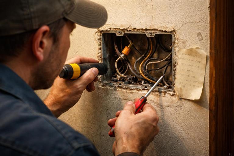
- 1) Identify the wiring method and condition. Open representative boxes (switch, receptacle, ceiling) and inspect conductor insulation, splices, and cable type. If insulation cracks when gently flexed, plan for conductor replacement or re-termination in accessible junctions rather than repeated handling.
- 2) Map the circuit path and junction locations. Determine where the feed originates, where it branches, and where neutrals are present. In older homes, the ceiling box often contains the neutral bundle even when the switch box does not.
- 3) Confirm grounding integrity. For metal boxes, verify bonding continuity back to the source. Do not assume metal raceway is an effective ground if fittings are loose, corroded, or interrupted by nonmetallic sections.
- 4) Check box fill and physical space. Count conductors and devices and compare to box volume. In retrofits, box fill is often the limiting factor that dictates whether you can install a deeper smart device, add pigtails, or must relocate the control.
- 5) Identify special circuit conditions. Look for MWBCs, shared neutrals, switched receptacles, and any sign of bootleg grounds or open neutrals. Verify with test instruments rather than assumptions.
- 6) Evaluate the load type and compatibility constraints. Note if the controlled load is a ceiling fan, transformer-fed lighting, old ballasts, or mixed lamps. In legacy systems, the load may be the reason a control fails, not the wiring.
- 7) Decide on the least invasive compliant path. Options include using the existing switch location, relocating the smart control to a box with neutral, using a relay module at the fixture, or using a hybrid approach (smart relay + existing mechanical switch as a low-voltage input, where permitted by the device design).
Strategy 1: Work with missing neutrals and switch loops without opening walls
Older homes frequently route power to the ceiling box first, then drop a two-wire cable to the wall switch (classic switch loop). In these cases, the switch box may have only a line and a switched leg, with no neutral. Rather than forcing a neutral into the box through invasive fishing, consider relocating the smart control function to where the neutral already exists.
Approach A: Install a smart relay/module at the fixture or junction with neutral
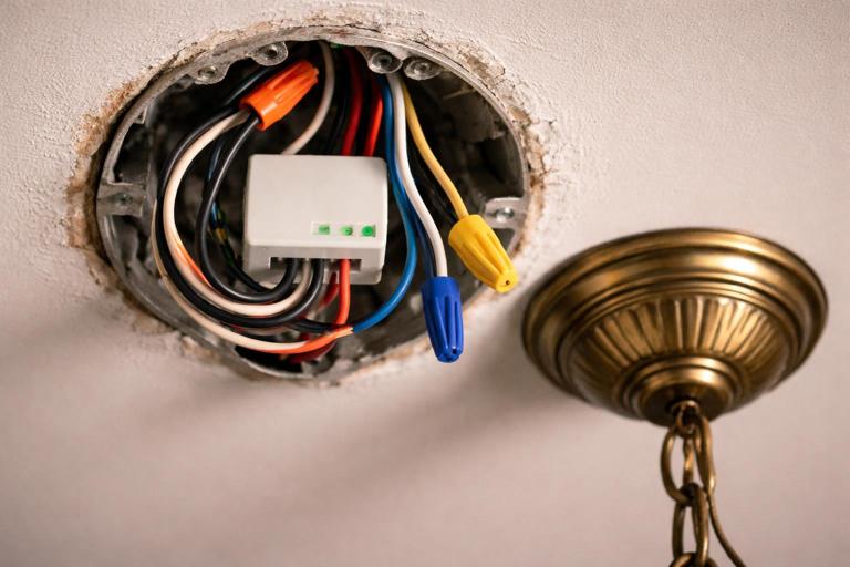
A compact relay module placed in the ceiling box or an accessible junction can provide smart control while keeping the existing wall switch as a simple on/off input (depending on the module’s design). This is often the cleanest retrofit when the switch box is shallow or lacks neutral.
- Listen to the audio with the screen off.
- Earn a certificate upon completion.
- Over 5000 courses for you to explore!

Download the app
Step-by-step: relay-at-fixture retrofit (switch loop scenario)
- 1) De-energize and verify. Lockout/tagout where appropriate and confirm absence of voltage at the fixture and switch.
- 2) Open the ceiling box and identify conductors. Typically you’ll find feed hot, feed neutral, and the two conductors going to the switch (one is always-hot to the switch, the other returns switched-hot).
- 3) Confirm box volume and heat considerations. Ensure the ceiling box can accommodate the module and all splices without overfill. If not, plan a larger listed box or an accessible junction extension (where allowed).
- 4) Wire the module per manufacturer diagram. Connect line and neutral to the module supply. Connect the module output to the load hot. Connect the wall switch conductors to the module’s switch input terminals if supported.
- 5) Re-identify conductors where required. If a white conductor is used as hot in the switch loop, re-identify it with tape/marker in all accessible locations.
- 6) Restore power and test local and smart control. Verify the wall switch input behaves as expected (toggle, momentary, or multi-tap depending on module settings).
- 7) Document the new topology. Place a circuit note inside the canopy/box cover if space allows and update panel/circuit documentation for future service.
Practical example: A 1950s hallway light has power in the ceiling box and a two-wire drop to the switch. The switch box is a shallow metal box in plaster. A relay module in the ceiling box avoids wall damage and avoids forcing a deeper box into plaster.
Approach B: Move the smart control to a location that already has neutral
Sometimes the best retrofit is to place the smart device in a different box on the same circuit that has neutral (for example, a nearby receptacle box), and then re-route the switched leg appropriately. This is only viable when the circuit layout and accessibility allow it and when the control location remains practical for the user.
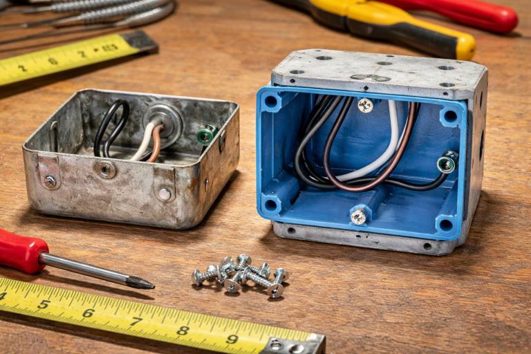
Strategy 2: Address small boxes and box fill constraints
Smart devices are often deeper than legacy toggles. In older homes, the limiting factor is not electrical theory but cubic inches. Overfilled boxes lead to damaged insulation, loose terminations, and overheating.
Common retrofit options for insufficient box volume
- Replace with a deeper old-work box: Works well in drywall; in plaster it may require careful cutting and reinforcement.
- Use a listed box extension ring: Useful for metal boxes where adding depth is acceptable and the finished surface alignment can be maintained.
- Reduce conductor count in the box: Move splices to an accessible junction (never bury), or reconfigure so fewer conductors enter the device box.
- Choose a different form factor: A relay module at the fixture may be easier than forcing a large smart switch into a shallow wall box.
Step-by-step: upgrading a shallow plaster switch box
- 1) Evaluate the wall construction. Plaster/lathe often crumbles; plan dust control and a clean cut line.
- 2) Determine if the existing box is nailed to a stud. If it is, removal may require cutting nails or using an oscillating tool carefully.
- 3) Select the replacement method. For minimal disturbance, a box extension ring may be preferable. If the device still won’t fit, use a deeper old-work box rated for the wall type.
- 4) Protect conductors during removal. Older insulation can crack; avoid pulling on cables. Support cables and maintain bend radius.
- 5) Re-terminate with pigtails as needed. Keep splices neat and short, and ensure the device can be installed without compressing conductors excessively.
- 6) Verify device mounting and faceplate fit. Ensure the finished surface is flush and the yoke is supported; use plaster ears or appropriate supports.
Strategy 3: Dealing with “no ground” realities in legacy circuits
Many older homes have two-wire circuits without an equipment grounding conductor. Smart devices and modern controls may require grounding for surge suppression, noise filtering, or safety. Even when a device does not strictly require a ground for operation, the installation must remain compliant and safe.
Retrofit decision points
- Is there a metal raceway or armored cable that provides a reliable ground path? Test continuity and impedance; do not assume.
- Is it feasible to add an EGC? Sometimes you can pull a grounding conductor through existing conduit, or run a new cable to the first accessible junction.
- Is the best option to leave the legacy circuit as-is and relocate smart control elsewhere? For example, control the load via a module at a grounded junction or replace the entire branch circuit when practical.
Practical example: A 1930s bedroom has two-wire NM feeding a switch and ceiling light. The homeowner wants smart control. If the ceiling box is metal but not reliably grounded, installing electronics there may be risky. A safer approach may be to run a new grounded feed to the ceiling box from an accessible attic junction, then install the control module.
Strategy 4: Mixed wiring methods and hidden junction risks
Retrofits often uncover transitions: knob-and-tube spliced to NM, old cloth cable spliced in a wall cavity, or conduit that ends unexpectedly. The key constraint is accessibility: all splices must remain in accessible junction boxes with covers. Smart retrofits can tempt installers to “tuck” a module into a cavity; avoid this. If a module must be installed, it must be in a listed enclosure with access for service.
Step-by-step: when you find an inaccessible splice
- 1) Stop and assess scope. Determine whether the splice can be made accessible by adding an access panel, relocating the junction, or rerouting the circuit.
- 2) Identify what the splice feeds. Map downstream loads to understand outage impact and to plan a reroute.
- 3) Choose a compliant remedy. Options include installing a new accessible junction box at the nearest accessible location and replacing the concealed segment, or opening the wall/ceiling to install a proper box with cover.
- 4) Document the change. Retrofits in older homes benefit from photos and notes for future troubleshooting.
Strategy 5: Multi-wire branch circuits (MWBCs), shared neutrals, and smart controls
Older homes may have MWBCs where two hots share a neutral. These can be perfectly serviceable when correctly wired, but they introduce constraints for smart retrofits because electronics may be sensitive to neutral integrity and because misidentified conductors are common in legacy work.
What to verify before adding smart devices on MWBCs

- Common disconnect and correct phasing: Ensure the two hots are on opposite legs so the neutral carries only the imbalance current.
- Neutral continuity and splice quality: A loose shared neutral can create overvoltage conditions on connected loads and can cause smart devices to reset or fail.
- Neutral separation errors: In older modifications, neutrals from different circuits may be tied together improperly, causing unpredictable behavior.
Step-by-step: MWBC retrofit verification (field method)
- 1) Identify the cable/conduit set. Look for a 3-conductor cable (or two hots in conduit) sharing a neutral.
- 2) Confirm handle ties/common trip at the panel. If missing, correct it as part of the retrofit scope where required.
- 3) Verify opposite legs. Measure voltage between the two hots; you should see nominal line-to-line voltage (e.g., ~240 V in a 120/240 system). If you see ~0 V, the hots are on the same leg and the neutral can be overloaded.
- 4) Inspect and rework neutral splices in accessible boxes. Use proper connectors and pigtails; avoid backstab terminations on devices in legacy circuits.
- 5) Test under load. Turn on representative loads on both legs and confirm stable voltage and device operation.
Practical example: A kitchen remodel from the 1980s left an MWBC feeding countertop receptacles and lighting. Adding smart undercabinet control modules causes random resets. Investigation finds a loose neutral wirenut in a crowded junction. Reworking the neutral splice and reducing box fill resolves the resets.
Strategy 6: Legacy lighting equipment that fights modern controls
Older homes often contain lighting equipment that behaves poorly with electronic controls: magnetic transformers, early electronic transformers, aging fluorescent ballasts, and mixed lamp types. Even if the wiring is acceptable, the load can cause flicker, ghosting, audible hum, or premature device failure.
Retrofit tactics for difficult legacy loads
- Bypass dimming where inappropriate: Use on/off control for loads that do not dim well.
- Isolate or replace problematic components: Replace old ballasts/transformers with compatible modern equivalents when feasible.
- Separate mixed loads: If a single switch controls multiple fixture types, consider splitting into separate controls if access allows.
- Use a relay/contact output rather than a triac dimmer: For certain transformers or motor loads, a relay-based control is more robust.
Step-by-step: diagnosing flicker in a retrofit
- 1) Confirm lamp/driver type. Identify whether the fixture uses LED retrofit lamps, integrated LED drivers, or legacy ballast/transformer.
- 2) Temporarily substitute a known-good load. If flicker disappears with an incandescent test lamp, the issue is load compatibility rather than wiring.
- 3) Check for shared neutrals and loose connections. Flicker can also be a symptom of neutral issues in older splices.
- 4) Choose the control method accordingly. Move from dimming to switching, or relocate the control module to the fixture and use a relay output.
Strategy 7: Routing new conductors with minimal disruption
Sometimes the only durable solution is adding a new cable or conductor. In older homes, the craft is doing it cleanly: using accessible pathways, minimizing patching, and avoiding structural damage.
Low-impact pathways commonly available in older homes
- Attics and knee walls: Often provide access above top plates for drops.
- Basements and crawlspaces: Allow feeding up into stud bays, especially near plumbing chases.
- Closets and utility chases: Good for vertical runs with minimal aesthetic impact.
- Existing conduit (where present): May allow pulling additional conductors if fill and condition permit.
Step-by-step: adding a new drop to a switch location (minimal patch method)
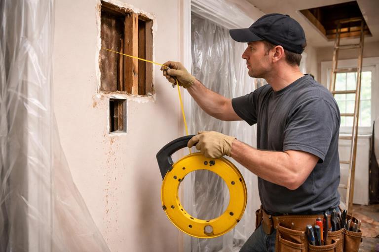
- 1) Select the best bay. Choose a stud bay with the fewest obstructions and the shortest path to an accessible top/bottom entry point.
- 2) Verify obstructions with inspection tools. Use a borescope or small inspection hole behind the future device plate area when appropriate.
- 3) Cut a precise opening for an old-work box. Keep the cut tight to reduce patching and ensure device support.
- 4) Drill top/bottom plates from accessible areas. Use proper drilling angles and protect finished surfaces. Install nail plates where required.
- 5) Fish the cable with controlled force. Avoid tearing insulation on lath or sharp edges; use bushings/grommets where needed.
- 6) Terminate and secure. Use proper connectors, strain relief, and staple/support requirements for the wiring method.
Strategy 8: Working safely with brittle insulation and aged terminations
In older homes, the act of opening a box can create new faults. Cloth and rubber insulation may crack, and old splices may be under tension. Plan to stabilize conductors rather than repeatedly bending them.
Best practices for fragile conductors
- Minimize movement: Support conductors while removing devices; avoid pulling cables out of the wall.
- Cut back to sound insulation: If insulation is cracked near the end, trim back and re-strip to clean material, provided you maintain adequate conductor length.
- Use pigtails to reduce stress: Terminate devices on new pigtails rather than repeatedly re-landing old conductors.
- Upgrade connectors: Replace old, overheated wirenuts and taped splices with listed connectors appropriate for conductor type and count.
- Use insulating sleeves/heat-shrink where appropriate: Only as a supplemental measure; do not “repair” unsafe wiring by covering widespread deterioration.
Step-by-step: stabilizing a crowded legacy switch box
- 1) Photograph before disturbing. Capture conductor routing and splice locations for reference.
- 2) Remove the device carefully. If conductors are short, plan for a box extension or rework to gain working space.
- 3) Rebuild splices with pigtails. Create a clean hot splice and neutral splice (if present) with short pigtails to the device, reducing the number of conductors under device screws.
- 4) Dress conductors intentionally. Fold conductors in layers to avoid sharp bends and pressure points against the device body.
- 5) Verify torque and retention. Loose terminations are a common retrofit failure in older wiring.
Strategy 9: Serviceability and documentation in retrofit smart integrations
Retrofits should be serviceable by the next electrician. Smart modules hidden in canopies, junctions, or multi-gang boxes need clear identification. Because older homes already have “mystery wiring,” your retrofit should reduce mystery, not add to it.
Documentation habits that prevent future troubleshooting headaches
- Label module locations: Note “smart relay in hall ceiling box” on the circuit directory or inside the nearest accessible junction cover.
- Record conductor re-identification: Especially in switch loops where white is repurposed as hot.
- Keep a simple as-built diagram: A one-page sketch showing where the control electronics live and how the wall switch interfaces.
- Leave manufacturer wiring diagrams: Store a printed diagram in the panel binder or homeowner packet.
Troubleshooting patterns unique to older-home retrofits
When a smart retrofit misbehaves in a legacy home, the root cause is often a pre-existing wiring weakness exposed by the new device’s electronics. Use symptom-based triage to avoid unnecessary device swaps.
Symptom: device reboots, drops offline, or behaves erratically
- Likely causes: Loose neutral splice, shared neutral issues, high-resistance connection, overloaded box causing heat, or intermittent grounding/bonding.
- Field checks: Measure voltage at the device under load, inspect neutral splices upstream, and check for MWBC misphasing.
Symptom: lights glow faintly when “off” or flicker at low levels
- Likely causes: Legacy load compatibility, leakage current through electronic controls, long switched-leg runs in old wiring, or mixed lamp types.
- Field checks: Substitute a different lamp type, isolate the load, or change to relay-based switching for that circuit.
Symptom: breaker trips only after retrofit
- Likely causes: Neutral-to-ground contact in a legacy box, shared neutral errors, damaged insulation disturbed during installation, or miswired MWBC neutral.
- Field checks: Inspect for pinched conductors, verify neutral isolation, and re-check all splices you touched in brittle wiring environments.
// Quick field note template (leave with job documentation)
Circuit: ____  Location: ____
Legacy constraints observed: [no neutral at switch] [no EGC] [shallow box] [MWBC] [brittle insulation]
Retrofit method used: [relay at fixture] [box extension] [new drop] [load split]
Module location(s): ____
Re-identified conductors: ____
Known limitations/notes: ____