Why the Boundary Matters: Two Electrical Worlds in One Smart Home
Smart homes routinely combine two very different electrical domains: line-voltage power distribution (typically 120/240 VAC in North America, 230 VAC in many other regions) and low-voltage control and signaling (commonly 5–48 VDC, sometimes 24 VAC for HVAC/doorbell, and data cabling for Ethernet or bus systems). The “boundary” is the point where these domains meet. Getting that boundary right is not just about functionality; it is about preventing shock hazards, fire risk, equipment damage, and hard-to-diagnose nuisance behavior (false triggers, random resets, communication dropouts).
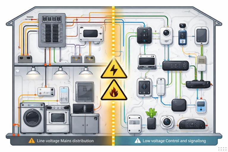
In practical terms, the boundary is managed by isolation, segregation, and correct interfacing components. A safe interface ensures that a fault on the line-voltage side cannot energize low-voltage conductors, metal device parts, or accessible terminals. A reliable interface ensures that switching transients, inductive kick, and noise do not corrupt low-voltage signals or destroy electronics.
Common places you will encounter the boundary
- Smart switches/dimmers controlling line-voltage loads while containing low-voltage electronics internally
- DIN-rail relay/contactor panels controlled by low-voltage inputs
- Garage door and gate operators (low-voltage control terminals) integrated with smart controllers
- HVAC thermostats and zone controls (often 24 VAC) integrated with home automation
- Doorbells (often 16–24 VAC) integrated with cameras and chimes
- Motorized shades and blinds (often low-voltage DC motors with line-voltage power supplies)
- Security sensors (low-voltage) triggering line-voltage lighting via relays
Definitions You Must Use Consistently on the Job
Line-voltage
Line-voltage conductors are those that can deliver hazardous energy directly from the premises wiring system. They are typically protected by branch-circuit overcurrent devices and are capable of delivering high fault current. Even when “off,” line-voltage wiring may remain energized in parts of a box (feed-throughs, multi-wire branch circuits, shared neutrals, etc.).
Low-voltage
Low-voltage in smart home work usually means control power or signaling that is limited by a listed power source (Class 2/Class 3 power supply, listed transformer, PoE source, etc.) such that the available energy is restricted. However, “low voltage” does not automatically mean “safe to mix anywhere.” Low-voltage circuits can still cause burns, arcing, equipment damage, and fire if miswired, and they can become hazardous if they are inadvertently connected to line-voltage or share enclosures incorrectly.
SELV/PELV/FELV (conceptual safety categories)
Depending on region and standards, you may see terms like SELV (Separated Extra-Low Voltage) and PELV. The key idea is whether the low-voltage circuit is separated from higher voltage by protective isolation and whether it is permitted to be referenced to earth/ground. When you are interfacing smart devices, you are often trying to preserve “separation” so that a single fault cannot elevate the low-voltage side to hazardous potential.
- Listen to the audio with the screen off.
- Earn a certificate upon completion.
- Over 5000 courses for you to explore!

Download the app
Core Safety Principles at the Boundary
1) Galvanic isolation when the low-voltage side is user-accessible or leaves the enclosure
If low-voltage conductors leave a box or panel and can be touched, serviced, or routed through the building, treat isolation as the default requirement. The most common ways to achieve galvanic isolation are:
- Electromechanical relays (coil isolated from contacts)
- Opto-isolated solid-state relays or optocouplers driving triacs/MOSFETs
- Listed transformers (for AC control power)
- Isolated DC power supplies (Class 2/limited power)
Non-isolated “buck” converters or capacitive droppers inside some devices may power electronics but do not provide safe separation for external low-voltage wiring. If a device offers low-voltage terminals intended for external wiring, verify that the manufacturer specifies isolation and the terminals’ rating/limits.
2) Physical segregation: keep conductors and terminations separated
Even with isolation, you must manage physical separation to reduce the chance of accidental contact, insulation damage, or mis-termination. Practical segregation methods include:
- Separate compartments in a panel (line-voltage side vs control side)
- Barrier dividers in enclosures and device boxes
- Separate conduit or raceway for line-voltage and low-voltage where required or where it improves reliability
- Maintain clear labeling and consistent color coding (especially in multi-conductor control cable)
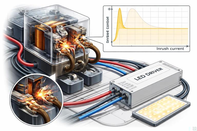
3) Correct ratings: voltage, current, and fault conditions
Interfacing components must be rated for the line-voltage they switch and the type of load (resistive, inductive, electronic driver). On the low-voltage side, ensure the power source is appropriate for the device input (dry contact vs powered input, AC vs DC, polarity, current draw). A common failure mode is using a relay module whose contacts are rated for “10 A resistive” to switch an LED driver or motor load with high inrush, causing welded contacts or premature failure.
4) Manage transients and noise at the boundary
Switching line-voltage loads creates electrical noise that can couple into low-voltage control wiring. Symptoms include random triggering, device reboots, missed commands, and communication errors. Noise control at the boundary typically uses:
- RC snubbers across relay contacts for inductive loads (when recommended)
- MOVs or surge protective devices on the line side (application-specific)
- Flyback diodes across DC relay coils (if not built-in)
- Twisted pair and proper routing for low-voltage control runs
- Separation from high-current conductors and motor circuits
Safe Interfacing Methods You Can Standardize
Method A: “Dry contact” interface (preferred when available)
A dry contact is an isolated switch closure with no voltage supplied by the smart device. Many automation controllers and smart relays provide dry-contact outputs specifically to interface with equipment that expects a simple contact closure (garage door operators, gate controllers, alarm panels, some boilers, some lighting contactors).
Why it’s safe: The dry contact provides galvanic isolation between the smart device electronics and the controlled equipment input. It also reduces the chance of backfeeding voltage into a sensitive input.
Step-by-step: using a dry contact to trigger a line-voltage load via a contactor
- Step 1: Identify the load switching device. Choose a contactor/relay rated for the load type and inrush. Confirm coil voltage (e.g., 24 VDC or 24 VAC).
- Step 2: Choose a listed control power source. Provide the coil power from a listed transformer or DC supply with appropriate rating (limited power where applicable).
- Step 3: Wire the dry contact in series with the coil circuit. The dry contact acts like a switch that energizes the coil. Keep coil/control wiring segregated from line-voltage conductors in the enclosure using barriers or separate wiring ducts.
- Step 4: Add coil suppression. For DC coils, add a flyback diode (observe polarity) unless the coil or module already includes suppression. For AC coils, use an RC snubber or MOV if recommended by the manufacturer.
- Step 5: Verify fail-safe behavior. Decide what happens on power loss or controller failure (contactor drops out vs stays energized). Select normally-open vs normally-closed logic accordingly.
- Step 6: Test with the load disconnected first. Confirm coil pull-in/drop-out, then connect the load and verify switching under normal and worst-case conditions (e.g., cold start for LED drivers).
Method B: Opto-isolated input modules for sensing line-voltage status
Sometimes you need to know whether a line-voltage circuit is energized (e.g., to confirm a fan is running, detect a pump call, or monitor a lighting circuit). Do not connect line-voltage directly to a controller input. Use a listed interface such as an opto-isolated sensing module, a current switch (current-sensing relay), or a voltage-sensing relay with isolated output.
Step-by-step: monitoring a 120/230 VAC signal with an isolated output
- Step 1: Define what you are sensing. Voltage present, current flowing, or equipment running. Choose a voltage-sensing relay for “voltage present” or a current switch for “current flowing.”
- Step 2: Confirm isolation and output type. Prefer devices that provide a dry-contact output or an isolated transistor output rated for your controller input.
- Step 3: Install the sensor on the line side per listing. Follow enclosure and wiring requirements. For current switches, route only the intended conductor through the sensor window.
- Step 4: Wire the isolated output to the controller input. Use the controller’s recommended input wiring (pull-up/pull-down, debounce if needed). Keep low-voltage wiring segregated.
- Step 5: Validate under real conditions. Test with the load on/off, and verify that inrush or standby currents do not cause false “on” indications. If they do, adjust sensor threshold or use a different sensing method.
Method C: Interposing relay (when a smart output cannot directly switch the target)
An interposing relay is a small relay used between a smart controller output and a higher-power switching device or incompatible input. It is common when:
- The controller output is low-current (e.g., transistor output) and needs to drive a coil
- You need to convert a powered output into a dry contact (or vice versa)
- You need additional isolation or different contact arrangement (SPDT/DPDT)
Key selection points: coil voltage matches your control supply; contacts rated for the circuit they will switch; relay is listed/recognized for the enclosure environment; suppression included or added.
Method D: Use a listed smart relay module with separated terminals
Some smart relay modules are designed specifically to sit at the boundary: line-voltage in/out on one side, low-voltage control terminals (or SELV power) on the other, with internal isolation and physical separation. When using these, verify:
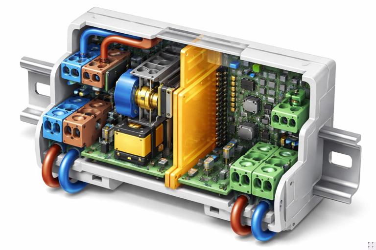
- Terminal labeling clearly separates mains vs SELV
- Clearances/creepage distances are maintained (do not defeat barriers)
- The low-voltage terminals are intended for external wiring (not just internal programming headers)
- The module’s installation instructions permit mixed wiring in the same enclosure and specify how
Enclosures, Boxes, and Routing: Practical Boundary Management
Mixed-voltage in the same box: when it becomes risky
Even if allowed by the device listing or local code practice, mixed-voltage in the same box becomes risky when low-voltage conductors can be mistaken for line-voltage conductors, when insulation ratings are mismatched, or when there is no physical barrier. Typical risk scenarios include:
- Low-voltage thermostat cable entering a 2-gang box with line-voltage splices and no divider
- Cat cable routed into a panel area where line-voltage conductors are dressed without wire duct separation
- Low-voltage conductors terminated on open screw terminals adjacent to line-voltage lugs
Best practice is to use separate compartments or separate boxes when the low-voltage wiring is not part of a listed assembly designed for co-location.
Routing rules of thumb that prevent troubleshooting later
- Do not bundle low-voltage control cable tightly with line-voltage conductors feeding dimmers, motors, or switched-mode power supplies.
- Cross line-voltage and low-voltage at 90 degrees when they must intersect.
- Use twisted pair for contact inputs and sensor loops to reduce induced noise.
- Keep relay coil wiring and contact wiring separated in wire duct; label both ends.
- Maintain service loops and strain relief so low-voltage conductors cannot be pulled into line-voltage terminations.
Interfacing Patterns You’ll Use in Smart Homes
Pattern 1: Low-voltage sensor triggers line-voltage lighting (relay interface)
Example: A low-voltage occupancy sensor output (dry contact or low-voltage signal) needs to control a line-voltage lighting circuit. The safe method is to use the sensor to drive a relay/contactor rated for the lighting load, with the relay providing isolation between the sensor wiring and the branch circuit.
Practical notes:
- If the sensor output is a transistor/open-collector, confirm it can drive the relay coil current or use an interposing relay.
- For LED lighting, select a relay/contact device rated for electronic loads or high inrush.
- Add suppression appropriate to the coil type to prevent sensor/controller resets.
Pattern 2: Smart controller interfaces to garage door/gate operator (momentary dry contact)
Most operators expect a momentary contact closure across two terminals. The safest interface is a dry-contact relay output that is isolated from the controller’s power. Configure the controller for a timed pulse (e.g., 0.5–1.0 seconds) rather than a maintained closure unless the operator documentation explicitly allows maintained closure.
Practical notes:
- Do not inject external voltage into the operator’s pushbutton terminals unless the manufacturer specifies it.
- Route the low-voltage pair away from motor power conductors to reduce false triggers.
- If false triggers occur, check for induced voltage on long runs and consider shielded cable or rerouting.
Pattern 3: 24 VAC systems (doorbell/HVAC) interfaced with smart devices
24 VAC is “low voltage,” but it is not the same as SELV DC logic. Many smart devices require specific wiring methods to avoid transformer overload, chime buzzing, or control board damage. Safe interfacing usually means one of the following:
- Use a listed interface module designed for that system (e.g., doorbell chime adapter, HVAC isolation relay)
- Use an isolation relay so the smart device does not directly load or backfeed the 24 VAC control circuit
- Provide a dedicated transformer/power supply for the smart device if required by the manufacturer
Key boundary idea: treat 24 VAC control circuits as their own domain with their own power source and limitations; do not assume you can share commons/returns with unrelated low-voltage DC systems.
Common Boundary Mistakes and How to Diagnose Them
Mistake 1: Sharing neutrals/returns between unrelated low-voltage supplies
Symptom: random triggering, unstable readings, communication dropouts, or a controller that resets when a relay energizes. Cause: tying together negatives/commons from different power supplies or mixing AC “common” with DC negative without a defined reference plan. Fix: keep supplies isolated unless the manufacturer explicitly requires a shared reference; if a shared reference is required, implement it at a single point and verify no unintended current paths.
Mistake 2: Driving a “dry contact” input with a powered output
Symptom: input never changes state, input is damaged, or equipment behaves unpredictably. Cause: applying external voltage to terminals that expect only a contact closure. Fix: use a relay output (dry contact) or an interposing relay to convert powered output to dry contact.
Mistake 3: Using a relay without suppression
Symptom: controller reboots when relay turns off, Wi-Fi/Zigbee device drops offline, or nearby sensors false-trigger. Cause: inductive kick from relay coil or load transients. Fix: add proper suppression (flyback diode for DC coils; RC snubber/MOV for AC coils or across contacts when appropriate), and improve wiring separation.
Mistake 4: Switching the wrong conductor or misidentifying “safe” wires
Symptom: device appears off but still has energized parts; low-voltage cable becomes energized after a fault. Cause: incorrect identification of conductors or improper separation in a shared enclosure. Fix: verify with appropriate test instruments, follow device diagrams, and enforce physical barriers and labeling so low-voltage cannot be confused with line-voltage.
Mistake 5: Underrated contact device for electronic loads
Symptom: relay chatters, welds closed, or fails after a short period; lights flicker or won’t turn off. Cause: inrush current and leakage characteristics of electronic drivers. Fix: use a contact device rated for the specific load type; consider a contactor designed for lighting loads or a relay with appropriate inrush rating; follow manufacturer guidance for maximum driver count per relay.
Field Workflow: A Repeatable Boundary Checklist
Step-by-step: verifying a safe low-voltage/line-voltage interface before energizing
- Step 1: Identify each circuit domain. Mark which conductors are mains, which are limited power, which are data/signal, and what their sources are.
- Step 2: Confirm the interface type. Dry contact, isolated input, interposing relay, contactor coil, or listed smart relay module. Do not proceed until you can describe the isolation method in one sentence.
- Step 3: Verify ratings at the boundary. Contact voltage/current/inrush on the line side; coil/input voltage and current on the low-voltage side; temperature and enclosure suitability.
- Step 4: Inspect physical segregation. Check for barriers, separate wiring ducts, strain relief, and that low-voltage insulation is not exposed near line-voltage terminations.
- Step 5: Add transient suppression where needed. Coil suppression, snubbers, surge protection per application. Confirm polarity for DC suppression devices.
- Step 6: Perform continuity and isolation checks (de-energized). Confirm no continuity between line-voltage conductors and low-voltage conductors except through intended isolated interfaces (relay contacts should be open when de-energized).
- Step 7: Power up in stages. Energize low-voltage supplies first and confirm stable operation; then energize line-voltage with loads disconnected if practical; finally connect loads and test switching.
- Step 8: Functional test plus fault-thinking. Test normal operation and consider what happens on power loss, controller reboot, network outage, and stuck relay. Verify the system fails in an acceptable state.
Practical Examples of Safe Interfaces
Example 1: Smart hub output (12 VDC transistor) controlling a 120 VAC bathroom fan
Safe approach: transistor output drives an interposing relay coil (12 VDC) with flyback diode; interposing relay contacts switch a fan-rated contactor or relay rated for the fan motor load. Keep the 12 VDC wiring in a segregated duct; keep the 120 VAC in a separate duct/compartment. If the fan has high inrush, select a switching device with appropriate motor/inductive rating.
Example 2: Monitoring a sump pump run status without touching the branch circuit
Safe approach: use a current-sensing switch around the pump hot conductor. The sensor provides an isolated dry contact to the automation input. This avoids direct electrical connection to the line-voltage circuit and reduces risk of introducing faults into a critical load.
Example 3: Integrating a low-voltage keypad with line-voltage lighting via a relay panel
Safe approach: keypad communicates or outputs low-voltage signals to a relay panel’s control inputs; the relay panel switches the lighting circuits. The relay panel is designed with separate line/control compartments and is installed per listing. This centralizes the boundary in one controlled location and keeps low-voltage wiring out of crowded switch boxes.
Documentation and Labeling at the Boundary (Prevents Unsafe Service Later)
Boundary problems often appear during future service when someone assumes all conductors in a box are the same class. Labeling is a safety control. At minimum:
- Label enclosure compartments: “MAINS” and “CONTROL/SELV”
- Label terminal blocks with voltage class and source (e.g., “24 VAC from XFMR T1”)
- Tag relay outputs with what they switch and whether they are dry contact or powered
- Document suppression components (diode direction, snubber location) so replacements are correct
When you standardize these boundary practices—galvanic isolation where needed, physical segregation, correct ratings, and transient control—you reduce both immediate hazards and the long-term service burden that comes with mixed-voltage smart home systems.