What “Multi-Way” Means in Modern Control
In residential and light commercial work, “multi-way switching” describes controlling one load (typically lighting) from two or more locations. Traditional wiring accomplishes this with 3-way (two locations) and 4-way (three or more locations) mechanical switches. In smart home integration, the same user expectation remains—tap at any location and the light responds—but the control topology can change dramatically. Instead of routing switched power through multiple mechanical devices, you may route control signals, use a single power-switching device with remote companions, or move the logic into a controller (hub, automation processor, or smart relay module).
A “conversion” is any change from one topology to another: mechanical 3-way to smart 3-way, mechanical multi-way to a single smart dimmer with companion, or mechanical multi-way to centralized relay control with low-voltage or wireless wall stations. Conversions are common during retrofits because existing cable types, box fill, and device locations constrain what is practical.
Control Topologies You’ll Encounter
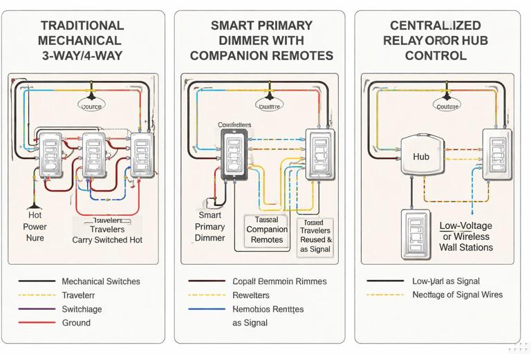
Topology A: Traditional Traveler-Based Switching (Mechanical 3-Way/4-Way)
This is the classic arrangement: line enters one box, load leaves another, and travelers run between. In a 3-way, two travelers connect the two switches; in a 4-way system, one or more 4-way switches sit between the two 3-ways, swapping traveler paths. The load is controlled by physically routing the hot conductor through the switch network.
When converting, the key challenge is that the “logic” is in the wiring itself. Smart devices often want a stable line feed and a stable load output at one location, while other locations become “remote controls” rather than power-routing switches.
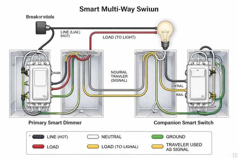
Topology B: Single Point of Power Switching + Companion/Remote Controls
Many smart multi-way solutions use one “primary” device that actually switches/dims the load, and one or more “companions” that send a control signal to the primary. The signal may travel over an existing traveler conductor, a dedicated control terminal, or be wireless. The primary needs access to both line and load conductors in the same box (or via a module at the fixture).
- Listen to the audio with the screen off.
- Earn a certificate upon completion.
- Over 5000 courses for you to explore!

Download the app
In this topology, the travelers are repurposed: instead of carrying alternating hot paths, they become a communication pair (or a single signal conductor plus reference). This is a common conversion strategy because it leverages existing multi-conductor cable between boxes.
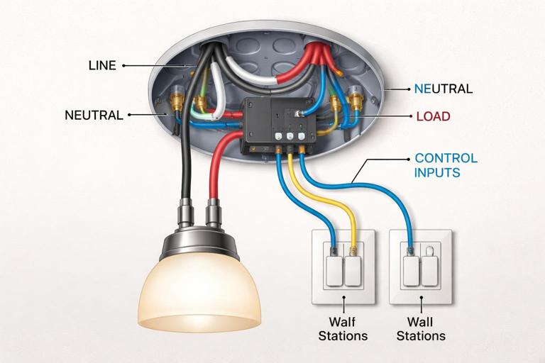
Topology C: Fixture/Canopy/Relay Module Does the Switching; Wall Stations Are Controls
Here, the switching element is moved to the load location (ceiling box, fixture canopy, junction box, or a DIN/structured panel). Wall devices become momentary inputs (hardwired) or wireless scene controllers. This is useful when neither wall box has both line and load, or when box fill is tight, or when you want multiple control points without running additional travelers.
For electricians, the practical shift is that you stop thinking of each wall device as a series power-routing element and start treating them as inputs to a controller. The load’s hot feed is switched at the module, and the wall controls provide commands.
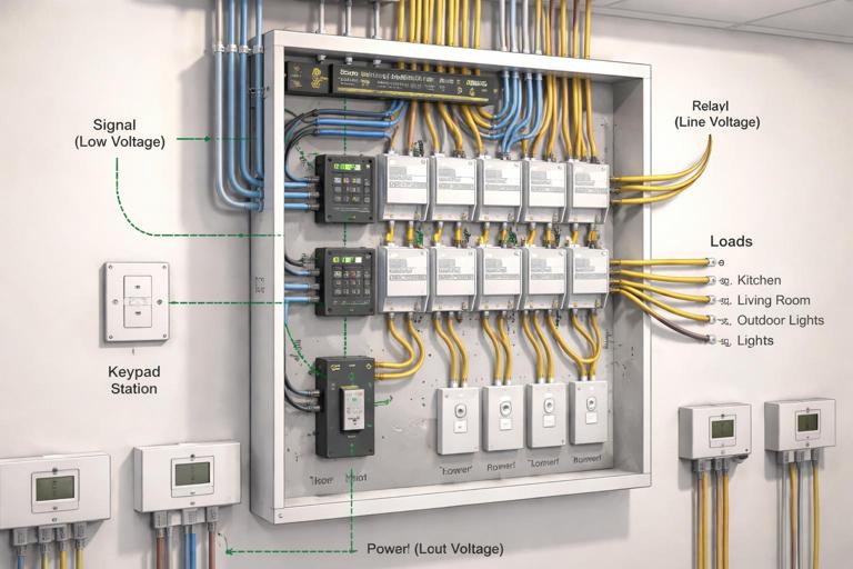
Topology D: Centralized Panelized Lighting (Relays/Dimmer Modules in a Panel)
In higher-end smart homes, loads are home-run to a lighting control panel with relay/dimmer modules. Wall stations are low-voltage keypads or smart keypads. Multi-way is purely logical: any keypad button can control any load. Conversions from traditional multi-way to panelized are major rewires, but partial conversions are possible when you can relocate switching to an accessible junction and repurpose existing conductors for control.
How to Identify the Existing Multi-Way Wiring Before Converting
Successful conversions start with positively identifying where line and load are, and how the travelers run. Multi-way circuits vary widely depending on which box receives the feed and which box sends the switched leg to the fixture.
Common Existing Arrangements
- Feed at one 3-way, load at the other: Most straightforward for a primary smart device if you can place it where both line and load are present (often not the case here).
- Feed and load both at the fixture: Switch boxes may only have travelers and a switch loop arrangement. This often pushes you toward a fixture module topology.
- Feed at fixture, load at fixture, travelers to switches: Similar to above; wall boxes may not have a constant hot suitable for a smart primary.
- Multiple 4-ways between 3-ways: Adds complexity; typically you’ll choose one location to become the primary and convert others to companions or momentary controls.
Field Mapping Workflow (Practical)
Use a repeatable mapping process so you don’t rely on assumptions about conductor colors or prior workmanship.
- Step 1: De-energize and lock out. Confirm absence of voltage at all involved boxes.
- Step 2: Photograph and label. Before disconnecting anything, take clear photos and label cables (e.g., “to fixture,” “to other switch,” “to next 4-way”).
- Step 3: Identify the 3-way “common” screws. On mechanical 3-ways, the common terminal is typically a darker screw. The conductor on common is either line (feed) or load (switched leg) depending on location.
- Step 4: Continuity test travelers. With conductors isolated, use a continuity tester to identify which conductors form the traveler pair between boxes. In multi-4-way runs, identify traveler-in and traveler-out pairs at each 4-way.
- Step 5: Determine where line and load are accessible together. This determines whether you can place a primary smart switch in a wall box or whether you should move switching to the fixture/module.
This mapping step is where most time is saved. Once you know where line and load coexist, the conversion choice becomes clear.
Conversion Strategy 1: Replace a Mechanical 3-Way with a Smart Primary + Companion
This strategy works when you can locate a box that contains both the always-hot feed and the switched leg to the load (or can be made to contain them by re-terminating within the existing cable paths). The other location becomes a companion/remote that does not switch the load directly.
Key Concept
The primary device becomes the only device that actually interrupts power to the load. The companion sends state changes to the primary over a repurposed traveler or a dedicated control terminal. The second traveler may be capped or used as a reference depending on manufacturer requirements.
Step-by-Step (Generic Workflow)
Always follow the specific wiring diagram for the device family you are installing; companion wiring differs across brands. The steps below describe the practical sequence electricians use on site.
- Step 1: Choose the primary location. Select the box where you have the best access to line and load conductors and adequate box volume for the smart device.
- Step 2: Remove the mechanical switches and isolate conductors. Separate the traveler conductors, common, and grounds. Keep them labeled.
- Step 3: Terminate line and load at the primary. Connect the always-hot feed to the primary’s line terminal and the switched leg to the load terminal.
- Step 4: Repurpose a traveler as the companion signal conductor. Choose one traveler (often red) to carry the companion signal. Cap the unused traveler if the system only needs one conductor, or use it as directed if a two-wire control link is required.
- Step 5: Configure the remote location. Install the companion device and connect it to the chosen traveler(s) and any required reference/line as specified by the device diagram. In many systems, the companion does not need the load conductor at all.
- Step 6: Re-check grounding and box fill. Smart devices are deeper; confirm conductors are neatly folded and no insulation is damaged.
- Step 7: Energize and functional test. Verify local control at the primary, remote control at the companion, and correct dimming behavior if applicable.
Troubleshooting Notes
- Remote does nothing: Most commonly the wrong traveler was selected, the traveler is not continuous end-to-end, or the companion requires a different reference connection than assumed.
- Load flickers or behaves inconsistently: Often indicates the primary is not actually switching the load conductor you think it is (misidentified switched leg), or the companion is wired into the load path incorrectly.
- Primary works but remote inverts behavior: Some systems require a configuration step (device parameter) to define multi-way mode; others auto-detect. Verify device settings.
Conversion Strategy 2: Convert a 4-Way (or Multiple 4-Ways) into Smart Multi-Location Control
When there are three or more control points, you typically keep one primary power-switching device and convert the remaining locations into companions or scene controllers. The main decision is whether to keep any traveler-based signaling between boxes or move to wireless/low-voltage controls.
Practical Approach: “Primary at an End, Remotes Everywhere Else”
In a classic 3-way/4-way/3-way chain, the end boxes contain the 3-ways and the middle boxes contain 4-ways. The end boxes are the best candidates for a primary because they often have either line or load on the common. If you can place the primary at the end that has both line and load (or can be rearranged to have them), do so.
Step-by-Step (Generic Workflow)
- Step 1: Map the traveler path through all boxes. Identify the two traveler conductors that run end-to-end through the chain.
- Step 2: Decide what becomes of the middle locations. Options include: (a) install compatible wired companions that use a traveler as signal, (b) convert middle boxes to momentary inputs to a module, or (c) install wireless scene controllers and cap travelers.
- Step 3: Eliminate traveler swapping. Mechanical 4-ways swap travelers; smart companions generally do not. Remove the 4-way switching function by re-terminating conductors so the chosen signal path is continuous (for example, splice traveler-to-traveler straight through in the middle box if allowed and if it matches the control scheme).
- Step 4: Install the primary and verify control signaling. Once the traveler path is no longer being swapped, the primary can interpret the remote signals consistently.
Because the middle boxes are often the most cramped, a common field tactic is to convert middle 4-way boxes into simple pass-through splices (maintaining conductor continuity) and place a wireless scene controller on the cover plate, leaving the box accessible with a listed blank/adapter as required by the installation method.
Conversion Strategy 3: Use a Fixture/Relay Module to Avoid Reworking Travelers
If neither wall box provides a clean “line + load in one place” situation, a module at the fixture or in an accessible junction can simplify the conversion. The module becomes the power-switching element, and the wall locations become control inputs.
Key Concept
You are separating power switching from user interface. The existing multi-way conductors can often be repurposed as low-current control inputs to the module (for example, momentary contact closures), or you can abandon the travelers and use wireless controls.
Step-by-Step (Generic Workflow)
- Step 1: Confirm module location and accessibility. Choose a location that remains accessible per code and practical service needs (fixture canopy, accessible junction, or serviceable enclosure).
- Step 2: Route unswitched power through the module to the load. The module takes line in and provides a switched/dimmed output to the fixture.
- Step 3: Convert wall switches to momentary or control stations. Replace mechanical 3-way/4-way switches with momentary switches or compatible input devices as required by the module. If reusing existing conductors, select a consistent pair for the control loop.
- Step 4: Program/configure input behavior. Define what a tap does (toggle, on, off, dim up/down) and how multiple inputs interact.
- Step 5: Test for predictable behavior from every location. Verify that rapid toggling, long-press dimming (if used), and simultaneous presses behave as expected.
Common Pitfalls
- Using existing travelers without verifying continuity: A traveler may pass through multiple boxes and be spliced; a hidden open can cause intermittent control.
- Leaving mechanical multi-way switching in place: If any mechanical 3-way/4-way remains in the power path, it can cut power to the module and make the system appear “dead.” In module-based topologies, wall devices should not interrupt the module’s supply unless the design explicitly calls for a service disconnect.
Control Topology Selection: Decision Points for Electricians
Where Are Line and Load?
If you can get line and load into one wall box without invasive rewiring, a primary smart switch with companions is usually the cleanest retrofit. If line and load are separated across boxes or only present at the fixture, a module-based approach reduces rework.
How Many Control Points and What User Experience Is Expected?
For two locations, most smart ecosystems handle a primary + companion well. For three or more locations, wireless scene controllers can be more reliable than trying to maintain a complex traveler signaling scheme through multiple intermediate boxes—especially if the existing wiring is inconsistent or crowded.
Is Dimming Required at All Locations?
Some systems allow dimming only at the primary, with remotes providing on/off. Others support full dimming from companions. If the customer expects press-and-hold dimming at every location, confirm the device family supports it before committing to a topology.
Do You Need Scene Control Instead of True Multi-Way?
In smart homes, the customer may actually want “scene” behavior: one button turns on multiple loads, another sets a dim level, another triggers an automation. In that case, converting a multi-way to a scene controller plus a single load controller can deliver more value than preserving a strict traveler-based multi-way.
Practical Examples of Conversions
Example 1: Two-Location Hall Light, Travelers Present, One Box Has Line and Load
In a hallway, you find that the feed enters the near-end box and the switched leg to the light also leaves that same box, while a 3-conductor cable runs to the far-end box. This is ideal for a primary smart switch at the near end. You install the primary there, repurpose one traveler as the companion signal, and install a companion at the far end. The load is only switched at the near end, but both locations control it.
Example 2: Staircase Light with 3 Locations (3-Way/4-Way/3-Way)
You map the circuit and find line at the bottom 3-way and load at the top 3-way, with a 4-way mid-landing. Rather than trying to keep the 4-way as a power-routing device, you choose a topology where the top box becomes the primary (because it has the load and can be rearranged to receive line via the traveler cable), and you convert the mid-landing to a companion or a wireless scene controller. In the mid-landing box, you re-terminate conductors so the chosen signal path is continuous and no traveler swapping occurs.
Example 3: Older Home Where Both Wall Boxes Lack a Clean Line+Load Pair
You open both 3-way boxes and find only travelers and a switched leg arrangement, with the feed and load spliced at the ceiling. Instead of forcing a smart primary into a wall box that cannot support it, you install a listed module at the ceiling box to switch the light. The two wall locations become momentary inputs (or wireless controls) that command the module. The customer gets reliable multi-way behavior without opening walls to reroute conductors.
Verification and Troubleshooting Workflow After Conversion
Functional Tests That Catch Most Errors
- Test each location independently: From each control point, turn the load on and off multiple times. Confirm the state remains consistent.
- Power-cycle test: Turn the breaker off and on. Confirm the system returns to a known state and remotes still control the load.
- Rapid toggle test: Tap quickly at different locations. Poor signaling, miswired companions, or marginal connections often show up here.
- Dim level consistency (if dimming): Set a mid-level at one location and confirm other locations report/track the same level (where supported).
Diagnosing “Works at One Location Only”
This symptom usually indicates the primary is wired correctly but the remote signaling is not. Check for: wrong conductor chosen as signal, traveler not continuous, a middle 4-way still swapping travelers, or a remote device that is not the correct companion type for that primary.
Diagnosing “Sometimes Works, Sometimes Doesn’t”
Intermittent behavior often points to a loose termination, backstabbed connection under load, or a traveler splice buried in a crowded box that is not making solid contact. In multi-location conversions, intermittent issues can also come from a control conductor that is accidentally tied to a switched leg in one box, causing unpredictable reference changes.
Documentation Practices for Serviceability
Multi-way conversions are notorious for confusing the next technician if the wiring no longer matches the “expected” 3-way/4-way pattern. Treat documentation as part of the installation.
- Label the primary location: Inside the box (on a tag) note “PRIMARY LOAD CONTROLLER” and identify which conductor is the control link to companions.
- Update the panel schedule or circuit notes: Indicate that the circuit uses a smart multi-way topology and identify the controlling device/module location.
- Leave a wiring diagram in the job folder: A simple sketch showing line, load, and control links saves hours later.
// Example field note format (keep with as-builts)
Circuit: Hall Lights (15A)
Primary controller: SW1 in Box A (north hall)
Load conductor: BLK to ceiling light
Control link to companion: RED traveler to Box B
Box B device: Companion (no load switching)
Middle boxes: N/A