Why jobsite testing matters in smart home integration
Smart home electrical integration adds layers of electronics, switching elements, and always-on loads that can behave differently than traditional “dumb” circuits. Jobsite testing with a multimeter and clamp meter is how you verify the basics (voltage, continuity, polarity, current, and leakage) and also confirm that smart devices are operating within expected electrical limits. The goal is not to “hunt for a reading,” but to follow a repeatable procedure that answers specific questions: Is the circuit energized and at the correct voltage? Is the neutral intact under load? Is current within device and breaker limits? Is there abnormal leakage or inrush that could cause nuisance trips or device resets?
This chapter focuses on field test procedures you can perform quickly and safely at rough-in, trim-out, and commissioning. It assumes you already know how the system is planned and wired; here you’ll learn how to validate and troubleshoot with measurements.
Tools and setup: what you need and how to use it correctly
Multimeter essentials
- True RMS multimeter (recommended) for accurate readings on non-sinusoidal waveforms from electronic loads.
- CAT rating appropriate for the environment (commonly CAT III 600 V for residential panels and branch circuits; follow your company standards and manufacturer guidance).
- Leads in good condition, with intact insulation and finger guards.
- Functions you will use most: AC volts, DC volts (for some control power supplies), resistance/continuity, diode test (occasionally), and capacitance (optional).
Clamp meter essentials
- AC current clamp with True RMS capability.
- Inrush capture (helpful for motors, transformers, and some LED drivers).
- mA range or leakage clamp (optional but very useful for diagnosing GFCI/AFCI nuisance issues and capacitive leakage from electronic loads).
- Jaw size that fits typical residential conductors and small bundles.
Basic meter handling rules that prevent bad data
- Prove your meter before and after: test on a known live source, take the measurement, then re-test on the known live source. This catches dead batteries, blown fuses, or wrong function selection.
- Start high, then go low: if you’re unsure of voltage, start with a higher range (or auto-range) and confirm before switching to more sensitive settings.
- One conductor in the clamp: clamping around a cable containing both hot and neutral will cancel current and read near zero. For branch current, clamp only the hot (or only the neutral) conductor.
- Stabilize your reference: for voltage checks, use a consistent reference point (line-to-neutral, line-to-ground, neutral-to-ground) and document which you used.
A repeatable jobsite test workflow
Use a consistent sequence so you don’t miss a condition. A practical workflow is: (1) visual and labeling check, (2) de-energized integrity tests, (3) energized voltage tests, (4) load tests with clamp meter, (5) targeted troubleshooting based on symptoms.
1) Visual and labeling check (before touching the meter)
- Confirm device model and rating match the circuit (voltage, load type, maximum current).
- Look for loose terminations, nicked insulation, overheated conductors, and mixed conductor sizes under one terminal.
- Verify neutrals are landed where expected and not doubled under terminals that don’t allow it.
- Check that splices are mechanically solid and that pigtails are used where required.
2) De-energized integrity tests (power OFF)
These tests help you find open neutrals, mis-identified conductors, and accidental shorts before energizing. Always verify de-energization with a meter (prove-test-prove) before switching to resistance/continuity.
Procedure: verify de-energized state
- Set meter to AC volts.
- At the device box or panel, measure line-to-neutral and line-to-ground. Confirm near 0 V.
- Prove your meter on a known live source again.
Procedure: continuity checks for conductors (selective, not random)
Continuity is most useful when you have both ends accessible (for example, panel to device box with the conductor disconnected at both ends). Do not continuity-test a circuit that may be connected to loads or electronics; you can get misleading readings or damage sensitive components.
- Listen to the audio with the screen off.
- Earn a certificate upon completion.
- Over 5000 courses for you to explore!

Download the app
- Disconnect the conductor at both ends (label it first).
- Set meter to continuity or resistance.
- Short the far end (temporarily tie the target conductor to a known return conductor) and verify continuity at the near end.
- Remove the short and confirm the reading returns to open/infinite.
Procedure: check for short to ground or neutral (insulation sanity check)
While a full insulation resistance test requires a megohmmeter, you can still catch gross faults with a standard meter.
- With conductors disconnected, measure resistance from hot to ground and hot to neutral. You should typically see open/infinite or very high resistance. A low resistance suggests a short or connected load.
- If you see moderate resistance, investigate whether a device, lamp, driver, or surge protector is still connected and providing a path.
Energized voltage tests: what to measure and how to interpret it
Core voltage checks at a device box
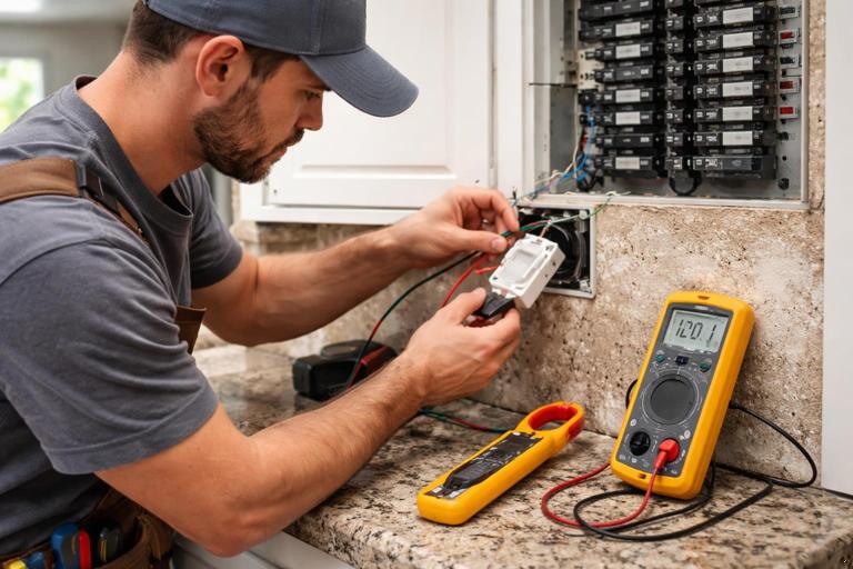
When troubleshooting smart switches, relays, or controlled receptacles, measure three voltages. Each tells a different story.
- Line-to-neutral (L-N): should be near nominal (e.g., ~120 V in North America). This is the primary supply voltage.
- Line-to-ground (L-G): should be similar to L-N. If L-G is correct but L-N is low or unstable, suspect a neutral issue.
- Neutral-to-ground (N-G): should be near 0 V under no load and typically low under load. Elevated N-G under load indicates voltage drop on the neutral path (loose neutral, shared neutral issues, long run, or high load).
Step-by-step: verify supply at a smart switch location
- Set meter to AC volts.
- Identify line (feed), load (switched leg), neutral (if present), and ground.
- Measure L-N at the line feed. Record the value.
- Measure L-G at the line feed. Compare to L-N.
- Measure N-G. If N-G rises significantly when the load is on, investigate neutral integrity and terminations upstream.
Testing the switched output (load terminal)
Smart switches may use electronic switching (triac/MOSFET) that can show “ghost voltage” on the load conductor when off, especially with high-impedance meters and LED loads. Don’t assume a small or unstable voltage means the circuit is energized in a dangerous way; verify with a load test.
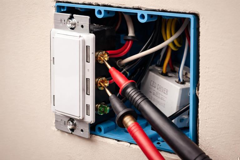
- With switch OFF, measure load-to-neutral. You may see a small voltage due to capacitive coupling or internal circuitry.
- Turn switch ON and measure load-to-neutral again. It should rise to near line voltage.
- If ON voltage is significantly low, suspect an overloaded device, a poor connection, or a failing driver/load.
Practical method: eliminate ghost voltage confusion
If you suspect ghost voltage, use one of these approaches:
- Use a low-impedance mode (LoZ) meter if available, which loads the circuit slightly and collapses induced voltage.
- Temporarily connect a known resistive load (for example, an incandescent test lamp or a purpose-built load tool) across the suspected conductor and neutral, then re-measure. If the voltage collapses, it was likely ghost voltage.
Clamp meter tests: current, inrush, and leakage
Measuring branch current correctly
Clamp meters measure magnetic field around a conductor. To get meaningful readings:
- Clamp around a single hot conductor feeding the load or device.
- Center the conductor in the jaw for best accuracy.
- Keep the jaw closed fully; even a small gap can cause errors.
Step-by-step: verify load current against expectations
- Turn on the controlled load(s) to a steady state (full brightness for dimmers, normal operating mode for appliances).
- Clamp the hot conductor feeding the load.
- Record steady-state current.
- Compare to device rating and breaker rating. If current is unexpectedly high, isolate loads one by one to find the contributor.
Inrush testing (when lights flicker, breakers trip, or devices reboot)
Some LED drivers, transformers, and motor loads draw a short inrush current that can trip protection or cause voltage sag that resets smart devices. If your clamp meter has an inrush function, use it.
- Set clamp meter to inrush mode.
- Turn the load off for at least 10–20 seconds (some drivers need time to discharge).
- Start inrush capture, then energize the load.
- Record peak inrush and compare across similar circuits or fixtures.
Interpretation tips:
- High inrush with normal steady-state current often points to driver/transformer characteristics rather than a wiring fault.
- If inrush is extreme only on one circuit, check for a specific fixture/driver model, a failing driver, or multiple drivers switching simultaneously.
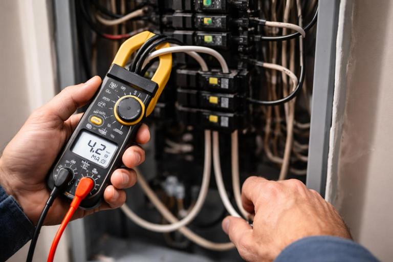
Leakage current testing (especially with GFCI-protected circuits)
Electronic loads and filters can create small leakage to ground. Individually it may be harmless, but multiple devices on one GFCI can add up. A leakage clamp meter (mA resolution) can help quantify it.
- Clamp around both hot and neutral together for a single circuit (this measures imbalance, which approximates leakage).
- With loads operating, read leakage current in mA.
- If leakage is high, isolate by turning off/unplugging devices one at a time and watch the leakage drop.
Note: Standard clamp meters may not resolve low mA leakage accurately. If you frequently troubleshoot nuisance trips, consider a dedicated leakage clamp.
Targeted troubleshooting scenarios and test procedures
Scenario A: Smart switch won’t power up (no LEDs, no response)
Objective: determine whether the device lacks supply voltage, has a neutral issue, or is defective.
Step-by-step
- At the switch box, measure line-to-neutral at the line feed. If ~0 V, the feed is missing (breaker off, open hot, miswire upstream).
- If L-N is low or fluctuating, measure line-to-ground. If L-G is normal but L-N is low, suspect an open/loose neutral.
- Measure neutral-to-ground. If you see elevated voltage under any load, tighten/repair neutral connections upstream (including at the panel and any junctions).
- If supply voltages are correct, check current draw: clamp the hot feeding the device (if accessible). Many smart switches draw a small standby current; if it’s near zero and voltage is correct, the device may be failed or not connected as intended.
Scenario B: Load works manually but smart device reboots or drops offline when load turns on
Objective: identify voltage sag, inrush, or shared neutral problems causing electronics to brown out.
Step-by-step
- Measure L-N at the device with load OFF, then again while switching the load ON. Watch for a dip.
- If your meter has min/max capture, enable it and cycle the load several times to catch brief sags.
- Use clamp meter inrush capture on the load conductor. Record peak inrush.
- Measure N-G while the load is ON. A rising N-G suggests neutral voltage drop under load.
- If sag is present, test at multiple points (device box and panel) to determine whether the drop is in the branch wiring or upstream supply.
Scenario C: Lights flicker on a smart dimmer
Objective: determine whether flicker correlates with unstable voltage, low load current, or driver behavior.
Step-by-step
- Measure line voltage L-N at the dimmer while flicker occurs. If voltage is stable, the issue is likely load/driver compatibility or wiring connection quality rather than supply fluctuation.
- Clamp the load current at a steady dim level and at full brightness. Very low current at dim levels can make some drivers unstable.
- Check for loose connections: flicker that changes when you move conductors or the device often indicates a termination issue. De-energize and re-terminate as needed, then retest.
Scenario D: Breaker trips when multiple smart loads turn on together
Objective: determine whether the trip is due to steady-state overload, inrush, or a fault.
Step-by-step
- With clamp meter, measure steady-state current with all loads on. If it exceeds breaker rating (or is close enough to cause heating), reduce load or redistribute circuits.
- If steady-state is acceptable, capture inrush while turning on the group. If inrush is high, stagger turn-on events during commissioning (where possible) or separate loads.
- If trips occur even at low current, investigate for fault: de-energize and perform resistance checks hot-to-neutral and hot-to-ground with loads disconnected where practical.
Scenario E: Controlled receptacle shows “hot” but appliance won’t run
Objective: distinguish between ghost voltage, open neutral, and a failed switching element.
Step-by-step
- Measure receptacle hot-to-neutral and hot-to-ground. If hot-to-ground is normal but hot-to-neutral is low, suspect open neutral.
- Measure neutral-to-ground under load (plug in a known load). If N-G rises significantly, neutral path is compromised.
- If voltage looks normal with no load but collapses under load, suspect a high-resistance connection (backstab, loose splice, damaged conductor) or a failing relay/contact.
- Use clamp meter on the receptacle feed hot. If the appliance is commanded on but current is near zero, the switching path may be open (device failure or miswire).
Documenting results: readings that help you fix problems faster
Write down readings in a consistent format so you can compare circuits and identify patterns. A simple field log for each problem circuit might include: location, breaker number, device model, L-N and L-G at device, N-G under load, steady-state current, inrush peak, and what changed when you isolated loads. This turns troubleshooting from guesswork into a controlled process and helps when you need to coordinate with other trades or the utility.
Practical measurement examples (with typical interpretations)
Example 1: Suspected open neutral at a smart switch
- Measured L-G: 121 V (stable)
- Measured L-N: 48–90 V (wandering)
- Measured N-G: 25 V with load on
Interpretation: Hot is present, but neutral reference is unstable and elevated under load. Focus on neutral splices/terminations upstream, including shared junctions and panel neutral bar connection for that circuit.
Example 2: Ghost voltage on switched leg
- Switch OFF, load-to-neutral reads 35–60 V on a high-impedance meter
- Applying a small resistive test load collapses voltage to near 0 V
Interpretation: Induced/phantom voltage, not a true energized condition. Confirm proper operation under load and use LoZ mode for future checks.
Example 3: Nuisance trips with multiple electronic loads
- Leakage clamp around hot+neutral: 4–6 mA with several loads on
- Removing one device drops leakage by 2 mA
Interpretation: Cumulative leakage is approaching a threshold where trips become likely. Isolate contributors and consider redistributing loads or replacing a particularly leaky device/driver.
Safety and accuracy reminders specific to jobsite testing
- Do not use resistance/continuity on energized circuits. Always verify de-energized state with voltage measurement first.
- Be cautious measuring in crowded boxes: use probe tips or accessories that reduce slip risk, and keep one hand away when practical.
- When clamping in panels, maintain conductor control and avoid disturbing terminations. If access is tight, measure at a safer downstream point.
- Remember that smart devices may have internal capacitors; after de-energizing, allow time for discharge before handling conductors.
Quick reference: what to test at each stage
Rough-in (before devices installed)
- De-energized continuity checks for identified runs (when both ends accessible).
- Resistance checks for gross shorts (hot-to-neutral, hot-to-ground) with loads disconnected.
Trim-out (devices installed, before full commissioning)
- Supply voltage checks L-N, L-G, N-G at representative device locations.
- Verify switched output behavior and identify ghost voltage correctly.
Commissioning (system operating)
- Clamp steady-state current on key circuits under normal use.
- Capture inrush on circuits that switch multiple drivers/transformers.
- Leakage/imbalance checks on circuits with protective devices where nuisance trips have been reported.