Why Shared Neutrals, Miswires, and Ground-Faults Matter in Smart Home Integration
Smart home devices often add electronics, sensing, and continuous standby loads to circuits that previously only fed simple switches and lamps. That extra complexity makes certain wiring defects show up more often: shared neutrals that are not handled correctly, miswired line/load or neutral/ground connections, and true or “leakage” ground-fault conditions. These issues can present as intermittent device resets, flickering, nuisance tripping, warm neutrals, unexplained voltage readings, or devices that won’t pair or stay online because their power supply is unstable.
This chapter focuses on identifying these conditions in the field and isolating the root cause efficiently. The goal is not just to “make it work,” but to leave a circuit that is electrically correct, stable under load, and predictable for future service.
Shared Neutrals (Multi-Wire Branch Circuits): What You’re Actually Looking At
A shared neutral typically means a multi-wire branch circuit (MWBC): two ungrounded conductors (hots) share one grounded conductor (neutral). In a correct MWBC, the two hots are on opposite legs of a 120/240V system so their neutral currents cancel (vector difference). In an incorrect MWBC, the two hots may be on the same leg, causing the neutral to carry the sum of the currents, which can overload the neutral and create erratic voltage behavior.
Common ways shared neutrals show up in smart home work
- Two lighting circuits in the same box share a neutral splice, and a smart switch is added to one circuit.
- A 3-conductor cable (e.g., black/red/white) feeds two separate switch legs with a shared neutral, and later modifications mixed the circuits.
- A receptacle circuit and a lighting circuit were tied together in a junction box, sharing a neutral unintentionally.
- Neutral splices in a multi-gang box were “cleaned up” and neutrals were separated incorrectly, leaving an open neutral for one leg.
Symptoms that suggest a shared neutral problem
- Smart dimmer/switch reboots when another load turns on (vacuum, microwave, LED driver, fan).
- Lights flicker only when a different circuit in the same box is loaded.
- Measured neutral-to-ground voltage rises noticeably under load.
- Breaker trips when two circuits are energized together, especially if a device ties neutrals internally (some smart devices reference neutral for power and sensing).
- One circuit appears “backfed” through another: a non-contact tester or meter shows phantom voltage on a conductor that should be dead.
Step-by-Step: Identifying a Shared Neutral in a Box
Use a structured approach so you don’t confuse a shared neutral with a bootleg neutral/ground tie or with induced/phantom voltage.
Step 1: Map what’s in the box (before disconnecting)
With power off, pull devices forward and visually identify the number of cables and their conductor colors. Look for:
- Listen to the audio with the screen off.
- Earn a certificate upon completion.
- Over 5000 courses for you to explore!

Download the app
- Two or more 2-conductor cables (black/white) plus a 3-conductor cable (black/red/white).
- Neutral bundle with multiple whites, possibly including a white from a 3-conductor cable.
- Two different breakers feeding the same box (common in multi-gang switch locations).
Tag each cable (A, B, C) with tape. Photograph the existing splices if needed for reference.
Step 2: Determine if multiple breakers feed the box
Turn on loads so you can see what goes off. Then, one breaker at a time, turn off and observe what de-energizes. If two breakers affect devices in the same box, treat it as a potential MWBC or mixed-circuit box.
Step 3: Confirm shared neutral with continuity (power off)
With both suspected breakers off, separate the neutral bundle carefully (keep conductors identified). Use continuity testing to see whether the neutral from Cable A is tied to neutral from Cable B elsewhere (for example, if neutrals are spliced through). Continuity alone won’t prove an MWBC, but it helps reveal whether neutrals are commoned beyond the box.
Step 4: Confirm with voltage relationships (power on, controlled)
Reassemble neutrals safely, energize one breaker at a time, and measure:
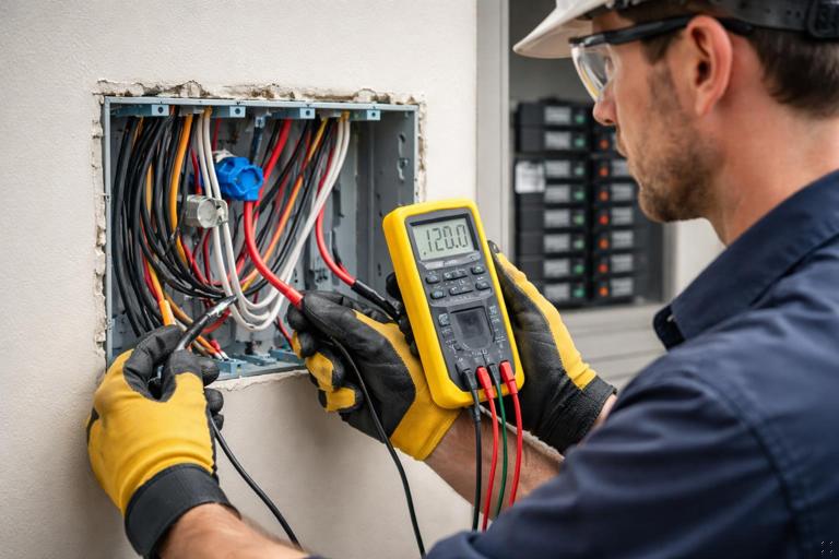
- Hot-to-neutral voltage on each circuit.
- Hot-to-hot voltage between the two suspected hots (black vs red, or black vs black from different cables).
Interpretation:
- If hot-to-hot is approximately 240V, the two hots are on opposite legs (typical correct MWBC condition).
- If hot-to-hot is approximately 0V (or very low), they are on the same leg, and a shared neutral would carry additive current (problem condition).
Also measure neutral-to-ground under load. A small voltage can be normal due to voltage drop, but a rising neutral-to-ground voltage that tracks load changes can indicate a loose neutral, overloaded shared neutral, or poor neutral connection upstream.
Step 5: Load test the neutral (practical confirmation)
Turn on a significant load on Circuit 1 (space heater, hair dryer, or a controlled test load). Measure neutral-to-ground and hot-to-neutral at the smart device location. Then turn on a load on Circuit 2 and watch for changes. In a correct MWBC on opposite legs, neutral current cancels partially and voltage stability is usually better. In a same-leg shared neutral, neutral drop increases and hot-to-neutral voltage can sag more noticeably.
Miswires That Mimic “Bad Devices”
Many “device failures” are actually wiring errors. Smart switches and dimmers are less forgiving than mechanical switches because they need stable supply power and may have internal sensing circuits that react to unexpected connections.
Line vs load reversal
Reversing line and load on a smart switch can cause:
- Device won’t power up (if it expects line at a specific terminal).
- Device powers but cannot control the load correctly.
- Load stays on dimly or flickers due to internal leakage paths.
Field check: With the switch removed and conductors separated, identify the always-hot feed (line) and the switched leg (load) by energizing the circuit and measuring each conductor to neutral. The line will remain hot regardless of switch position; the load conductor will only become energized when connected through the device or when the switch closes (depending on configuration).
Switched neutral (neutral being opened instead of hot)
A switched neutral is a classic miswire that can be hard to spot in a crowded box. It can leave the load energized relative to ground even when “off,” and it can confuse smart devices that expect neutral to be a stable reference.
Symptoms: Lamp socket shell or fixture wiring reads hot-to-ground even when switch is off; smart device behaves erratically; unexpected voltage on load conductor when “off.”
Field check: At the fixture, measure between the supposed neutral and ground with the switch off. If the “neutral” is not at or near ground potential and instead floats or reads energized, suspect a switched neutral or open neutral.
Borrowed neutral (neutral from a different circuit)
A borrowed neutral occurs when a hot from one circuit uses a neutral from another circuit. This can happen during remodels or when someone “needed a neutral” in a box and grabbed one from a nearby bundle. It can cause breaker trips, overheated neutrals, and unpredictable behavior when circuits are loaded differently.
Symptoms: Device works until another circuit is turned on; neutral-to-ground voltage fluctuates; breakers trip when both circuits are on; smart device resets when unrelated loads operate.
Field check (practical): Turn off Breaker A and see if the device still has any voltage present hot-to-neutral. If it does, the neutral may be tied to a different energized circuit. Another method is to turn off Breaker B and see if the “neutral” loses its reference (voltage readings become unstable). The most reliable confirmation is to isolate neutrals and verify which neutral belongs to which hot by controlled energization and measurement.
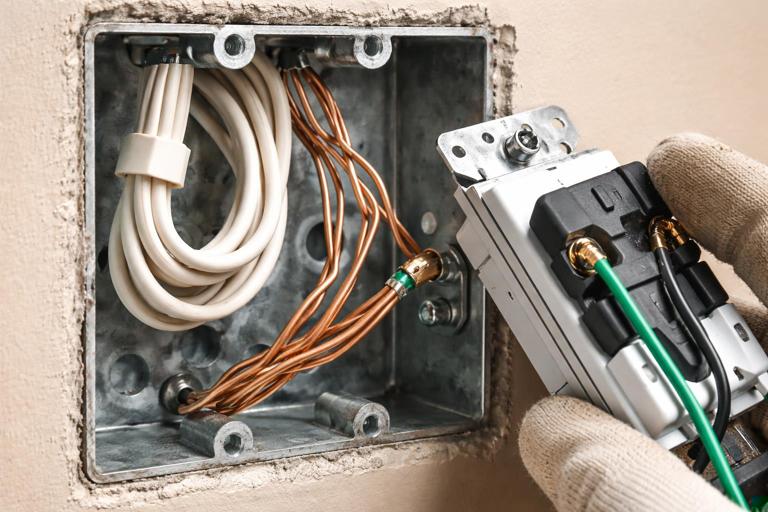
Neutral/ground mix-ups and bootleg connections
In device boxes, a neutral conductor might be incorrectly landed on a ground terminal, or a ground might be used as a return path. In receptacles, a bootleg neutral-ground bond can mask an open neutral and create dangerous touch voltages on metal parts.
Symptoms: GFCI behavior becomes unpredictable; metal yokes or plates show measurable voltage; smart devices show “ground fault” or fail self-tests; nuisance tripping when other loads run.
Field check: Visually inspect terminations: neutrals should be on neutral terminals and in neutral bundles; grounds should be bonded to the box and device yokes. If you see a jumper between neutral and ground at a receptacle or in a device box, treat it as a serious defect and correct it by restoring a proper neutral path rather than bonding locally.
Ground-Fault Conditions: True Faults vs Normal Leakage
A ground-fault condition exists when current returns to the source by any path other than the intended neutral (for example, through equipment grounding conductors, metal boxes, conduit, building steel, plumbing, or a person). In modern homes, some amount of leakage current can be normal due to EMI filters in power supplies, LED drivers, and smart device electronics. The troubleshooting challenge is distinguishing acceptable leakage from a fault that indicates damaged insulation, moisture intrusion, pinched conductors, or miswiring.
Common causes of ground-faults in smart home circuits
- Staple or screw through cable insulation contacting a metal stud or box.
- Moisture in exterior boxes, landscape lighting transformers, or damp locations.
- Neutral touching ground in a downstream device or junction (creating parallel return paths).
- Damaged cord-connected load plugged into a controlled receptacle.
- Miswired smart switch where neutral is tied to ground to “make it work.”
Symptoms
- GFCI trips immediately when a load is connected or when a smart device powers up.
- Trip occurs only when humidity is high or after rain (exterior circuits).
- Trip occurs only when a particular appliance is used.
- Intermittent trip when dimming (some drivers leak more under certain waveforms).
Step-by-Step: Isolating a Ground-Fault on a Branch Circuit
This workflow assumes you have access to the panel and the affected devices, and you can disconnect loads safely. The aim is to split the circuit until the fault is located.
Step 1: Separate “wiring fault” from “load fault”
Unplug all cord-connected loads on the circuit (including anything controlled by smart plugs or receptacles). If the circuit still trips with nothing plugged in, suspect fixed wiring, a device, or moisture in a box. If it stops tripping, plug loads back in one at a time to identify the offending appliance.
Step 2: Identify whether the fault appears with the smart device disconnected
At the smart switch/receptacle location, disconnect the load conductor and cap it. Energize the circuit. If the device holds without tripping, the fault is likely downstream on the load side (fixture wiring, cable to fixture, or the fixture itself). If it still trips, the fault may be in the line feed, the device, or in a neutral/ground contact in the box.
Step 3: Divide the circuit at the most accessible junction
Find the first downstream junction point (often the nearest receptacle, a lighting junction, or the next box in the run). Disconnect the downstream hot and neutral leaving that box (keep line feed intact). Energize and observe. Repeat this “divide and conquer” method until the segment containing the fault is identified.
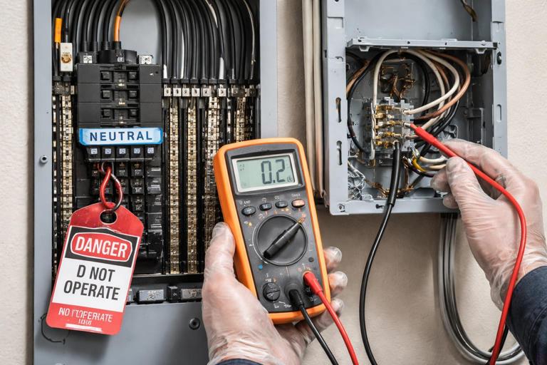
Step 4: Check for neutral-to-ground contact downstream (power off)
With power off and neutrals isolated from the neutral bar if possible (or at least isolated in the suspect segment), test for continuity between neutral and ground in the downstream segment. A solid continuity reading suggests an improper neutral-ground bond or a fault where neutral is contacting grounded metal. Be aware that connected loads with EMI filters can show some continuity-like behavior; to reduce confusion, disconnect electronic loads and drivers when possible.
Step 5: Inspect high-probability physical points
- Boxes with crowded splices where bare ground can touch neutral screws.
- Metal boxes where insulation may be nicked at the clamp.
- Exterior boxes and fixtures for water tracks, corrosion, or damaged gaskets.
- Recently installed trim screws that may be too long.
Interpreting Confusing Readings: Phantom Voltage, Floating Neutrals, and Backfeed
Modern meters have high input impedance and will display induced or capacitively coupled voltage on open conductors. Smart home wiring often runs in the same cable or conduit with energized conductors, increasing the chance of phantom readings.
Phantom voltage on a disconnected load conductor
If a load conductor is disconnected and you read, for example, 30–90V to neutral, that may be induced voltage. The key is whether it can deliver current.
Practical verification: Apply a known small load (for example, a solenoid tester or a low-impedance mode if your meter supports it). If the voltage collapses, it was phantom. If it holds, you may have a backfeed through a connected load, a miswire, or a shared neutral situation.
Floating neutral behavior
An open neutral can cause wildly varying voltages, especially when loads are connected. In shared-neutral scenarios, a loose neutral splice can create symptoms that look like device failure: lights brighten/dim unexpectedly, smart devices reboot, and measured voltages change when other loads operate.
Practical check: With a load on, measure voltage drop across suspect neutral connections (from neutral conductor to neutral bundle, or across wirenuts using safe probing). Any measurable drop across a connection indicates resistance where there should be essentially none, pointing to a loose or failing splice.
Smart-Device-Specific Clues That Point to Wiring Defects
Device powers up but drops offline when a load changes
This often indicates a supply stability issue: loose neutral, shared neutral on same leg, or high resistance connection. Smart devices typically have a small power supply that is sensitive to dips and noise. If the device reboots when a different load starts, focus on neutral integrity and shared neutral configuration rather than the device firmware.
Dim glow when “off” on LED loads
While some off-state glow can be normal with certain dimmers and LED drivers, it can also be a clue that line/load is reversed, neutral is not actually neutral, or the load is being backfed through another circuit (borrowed neutral or miswired multi-gang). Treat persistent glow plus other symptoms (flicker, resets, tripping) as a wiring investigation, not just a compatibility issue.
GFCI trips only when the smart device is connected
This can happen if the device has internal leakage that pushes an already leaky circuit over the threshold, but it can also indicate a neutral/ground mix-up in the box or a shared neutral crossing through a protective device in an unintended way. The practical approach is to temporarily remove the device and restore a simple pass-through (or a standard switch) to see whether the trip behavior changes, then isolate downstream segments.
Field Workflow: A Repeatable Diagnostic Sequence
When you walk into a service call with “smart switch not working,” use a consistent sequence to avoid chasing symptoms:
- Identify all circuits present in the box and whether more than one breaker feeds it.
- Verify line, load, neutral, and ground are correctly identified and terminated.
- Check for shared neutral indicators (3-conductor cable, multiple circuits, hot-to-hot measurement).
- Look for borrowed neutral signs (device still reads voltage with one breaker off, unstable readings, cross-circuit behavior).
- If tripping is involved, separate load vs wiring by disconnecting downstream loads and dividing the circuit.
- Inspect and re-make any suspect neutral splices; many intermittent issues are mechanical connection problems.
Practical Examples
Example 1: Two smart switches in a 2-gang box, one reboots when the other turns on
Observed: Switch A controls kitchen cans; Switch B controls under-cabinet lights. When B turns on, A reboots and the cans flicker.
Likely causes to test: Shared neutral on same leg, loose neutral splice, or borrowed neutral between circuits.
Steps:
- Determine if A and B are on different breakers.
- Measure hot-to-hot between the two line feeds. If near 0V, they are on the same leg; investigate MWBC correctness and neutral loading.
- Re-make the neutral splice with proper connector sizing and conductor prep; repeat load test.
- If breakers are different, verify neutrals are not crossed between circuits in the box.
Example 2: GFCI trips when exterior smart switch is installed, but not with a mechanical switch
Observed: Exterior lights trip the GFCI only when the smart switch is connected.
Likely causes to test: Existing leakage/moisture plus added device leakage, neutral-to-ground contact in exterior box, or miswire where neutral is tied to ground to power the device.
Steps:
- Disconnect the load to the exterior lights and energize the smart switch alone. If it holds, fault is downstream.
- Inspect exterior fixture and box for moisture and damaged insulation.
- With power off, isolate downstream neutral and test neutral-to-ground continuity; if solid, locate the neutral-ground contact point.
- Reconnect stepwise until the trip returns, identifying the exact segment or device causing imbalance.
Example 3: “Dead” smart switch after installation, but meter shows voltage
Observed: Meter shows 60V on the supposed line conductor; device will not power.
Likely cause: Phantom voltage on an open conductor or backfeed through a load; actual line feed is different conductor.
Steps:
- Use a low-impedance test method to see if the 60V collapses.
- Identify the true always-hot by measuring each candidate conductor hot-to-neutral with a known neutral reference.
- Verify neutral is present and solid; a missing/open neutral can also cause “voltage present but no power” behavior for electronics.