Why Documentation and Labeling Matter in Smart Home Electrical Work
Smart home electrical integration adds layers of complexity beyond traditional residential wiring: devices may be line-powered but configured in software, loads may be controlled by multiple logical triggers, and future service calls often start with “something changed in the app.” Good documentation and labeling turn that complexity into a maintainable system. The goal is that another electrician (or you, six months later) can open the panel, a switch box, or a structured wiring area and quickly answer: What is this device? What does it control? Where is it fed from? How is it intended to operate? What credentials or configuration details are needed to service it?
Maintainable install standards are the practical rules you follow so the physical work supports long-term serviceability: consistent labeling, predictable wire management, accessible junctions, documented spares, and a clean handoff package. This chapter focuses on what to record, how to label, how to hand off to the homeowner, and what “service-ready” workmanship looks like on smart-enabled jobs.
Documentation Deliverables: What to Produce on Every Job
Documentation should be sized to the project, but even small jobs benefit from a consistent set of deliverables. Think in three layers: electrical (what is wired), control (what is configured), and operational (how the homeowner uses it).
1) Electrical As-Built Package
- Panel schedule (as-built): breaker number, amperage, circuit name, areas served, and any smart-controlled loads tied to that circuit.
- Device inventory: make/model, location, and what each device controls (load name). Include any in-wall modules, DIN-rail modules, power supplies, and hubs/bridges.
- Box-level notes: for each smart switch location, note line feed source (if known), load, travelers/aux wiring (if present), and any special wiring constraints (e.g., “shared box with fan control,” “two-gang with mixed circuits”).
- Junction and splice map: list any junction boxes used for smart modules, power supplies, or load grouping, with a short description of contents.
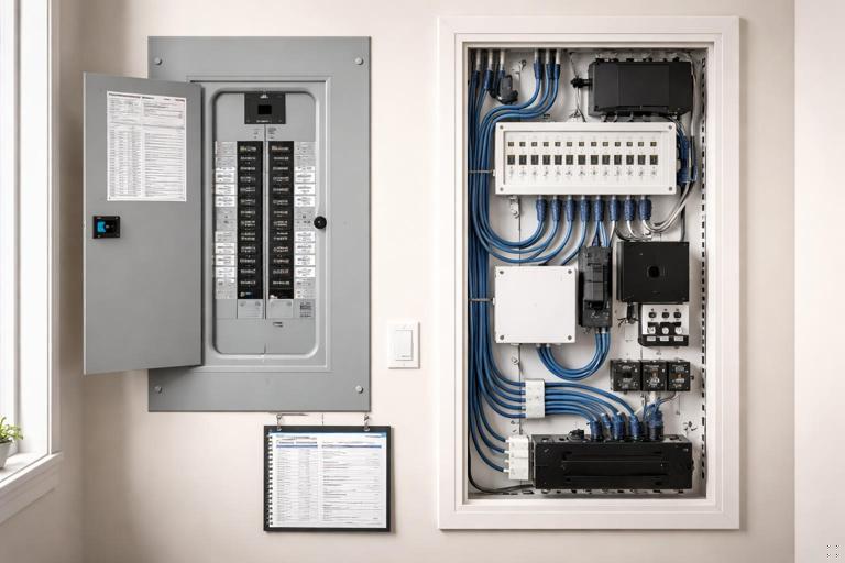
- Photos: inside panel (deadfront removed), each smart device before plate install, any junctions, and any structured wiring area. Photos are often the fastest “as-built.”
2) Control/Configuration Record
- Logical names: the exact names used in the app/automation system for each device and each load/scene.
- Room/zone mapping: which devices belong to which rooms, and how zones are defined (e.g., “Kitchen: Pendants, Cans, Under-cabinet”).
- Automation summary: a list of automations/scenes created, with triggers and actions (e.g., “Goodnight: turn off first floor lights, lock doors, set thermostat to 68°F”).
- Network dependencies: what hub/bridge is required, where it is located, and what power/UPS it is on.
- Firmware/app versions at handoff: record versions at completion so later behavior changes can be compared.
3) Homeowner Operations Packet
- Quick-start guide: how to use key switches, scenes, and overrides without needing you.
- Reset and recovery basics: what to do after a power outage, router replacement, or if a device stops responding (high-level steps, not deep troubleshooting).
- Warranty and support: device warranty info, your service policy, and who to call for what (electrician vs ISP vs automation vendor).
- Safety notes: what not to do (e.g., “Do not replace smart dimmer with standard dimmer without checking load type,” “Do not paint over sensors”).
Labeling Standards: Make It Obvious, Durable, and Consistent
Labeling is not just for the panel. A maintainable smart home has labels at the panel, at devices, at junctions, and sometimes on cables. The key is consistency: a naming convention that ties physical labels to documentation and to app names.
Choose a Naming Convention (and Stick to It)
A practical convention is: [Area]-[Load]-[Type/ID]. Examples:
- Listen to the audio with the screen off.
- Earn a certificate upon completion.
- Over 5000 courses for you to explore!

Download the app
- KT-Pendants-SW1 (Kitchen pendants switch 1)
- LR-Cans-DIM1 (Living room cans dimmer 1)
- EXT-FrontPorch-LT (Exterior front porch light)
Match the app name closely to the physical label. If the wall plate says “KT Pendants,” the app should not say “Light 7.” Small mismatches create long-term confusion.
Panel Labeling
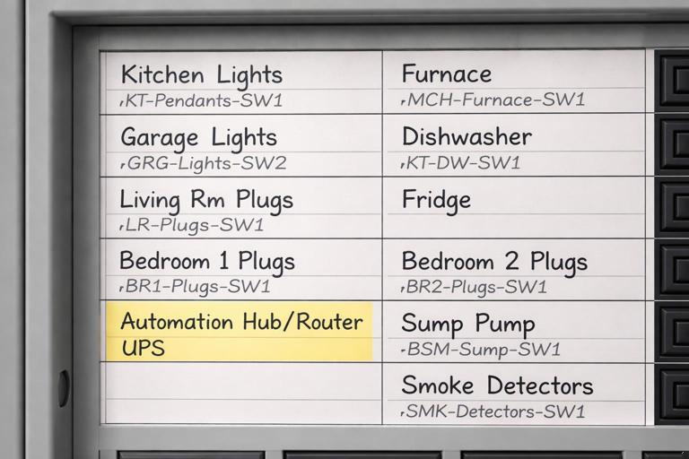
Panel schedules should be legible, durable, and updated to match the final as-built. Use a printed directory if possible. For smart homes, add a second line when needed: the primary area served and the key controlled loads.
- Good: “15A KT Lighting (Pendants/Cans)”
- Better: “15A KT Lighting (KT-Pendants-SW1, KT-Cans-DIM1)”
If a circuit feeds a hub, bridge, or power supply, label it clearly (e.g., “Automation Hub/Router UPS”). This helps future troubleshooting when a homeowner reports “everything is offline.”
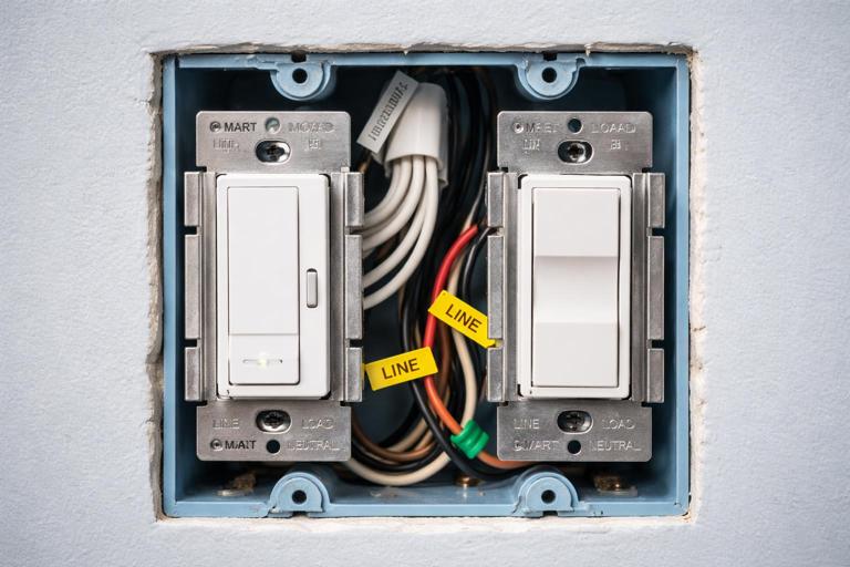
In-Box and Device Labeling
For in-wall smart switches/dimmers, the visible label is usually the wall plate engraving or a small label inside the cover plate. For serviceability, also label inside the box when practical:
- Inside-box tag: a small wrap label on the device yoke or a short note on a tag tied to the equipment ground (where allowed by your standards) indicating the load name and circuit number.
- Multi-gang boxes: label each device with its load name; do not rely on left-to-right memory.
For modules hidden in junction boxes or above ceilings, labeling is critical. Put a label on the junction box cover: “Smart relay inside: controls KT-UCab; fed from CKT 12.”
Cable and Conduit Labeling
Where you have a structured wiring area, a control cabinet, or multiple similar runs, label both ends of each cable. Use heat-shrink or wrap labels that won’t fall off. Include destination and purpose:
- “To KT Switch Box / Control link”
- “To Garage / Door operator power”
- “To Rack / Hub LAN”
Even if you are not the low-voltage contractor, labeling any cables you install or reroute reduces finger-pointing later.
Step-by-Step: Build an As-Built Package During the Job (Not After)
The easiest way to meet documentation requirements is to collect information as you work. Waiting until the end leads to missing details and rushed guesses.
Step 1: Start a Device and Load Register
Create a simple table (paper or digital) with columns: Area, Physical location, Device type, Model, Circuit/breaker, Load controlled, App name, Notes. As each device is installed, add it immediately.
Area | Location | Device | Model | Breaker | Load | App Name | NotesPractical tip: assign temporary IDs (SW1, SW2…) during rough-in, then replace with final names at trim-out.
Step 2: Photograph Before Closing
Take consistent photos:
- Panel interior with breaker numbers visible.
- Each smart switch box showing conductors and device before plate.
- Each junction box with smart module before cover.
- Any power supplies, hubs, or control cabinets showing connections.
Name photos using the same convention (e.g., “KT-Pendants-SW1_box.jpg”). A folder of well-named photos can serve as a functional as-built even if drawings are minimal.
Step 3: Update the Panel Schedule as Changes Happen
Smart home jobs often involve last-minute changes: a load gets moved to a different circuit, a device is swapped, or a room gets re-zoned. Update the schedule immediately when a change is made. If you wait, you will forget which “temporary” breaker became permanent.
Step 4: Record Configuration Decisions
When you name a device in the app, write it down exactly. When you create an automation, record trigger/action. If you adjust a default setting (e.g., LED indicator behavior, default dim level, fade rate), note it. These details matter when a homeowner says, “It used to fade smoothly and now it snaps on.”
Step 5: Produce a Homeowner-Facing Quick Guide
Keep it short and task-based. Example sections:
- “How to turn on Kitchen scenes from the wall.”
- “How to override motion behavior.”
- “What to do if the internet is down.”
Homeowners rarely read long manuals, but they will use a one-page cheat sheet.
Maintainable Install Standards: Physical Work That Supports Future Service
Documentation helps, but the installation itself must be serviceable. The following standards reduce callbacks and make future modifications safer and faster.
Box Fill, Conductor Management, and Service Loops
Smart devices can be deeper than standard switches and may require more conductors. Maintainability means:
- Leave usable conductor length: enough to pull the device out for service without stressing terminations.
- Organize conductors: group line, load, neutral, and travelers consistently; use approved wire connectors and avoid “mystery splices.”
- Minimize rework damage: avoid nicked insulation and over-stripped conductors; these become intermittent faults later.
Practical example: In a two-gang box with a smart dimmer and a smart switch, route neutrals as a neat bundle in the back with a single pigtail to each device, rather than a chain of splices that is hard to inspect.
Accessible Junctions and Clear Covers
If a smart relay/module is placed in a junction box, that box must remain accessible and identifiable. Maintainable standards include:
- Do not bury junctions behind drywall or cabinetry.
- Use a cover that can be removed without disassembling finished work.
- Label the cover with the controlled load and circuit reference.
This is especially important when modules are used to control multiple loads from a single location; future electricians must be able to find the control point.
Dedicated Power and Protection for Critical Smart Infrastructure
Many smart systems depend on always-on devices (hubs, bridges, routers, PoE switches, power supplies). Maintainability improves when these are treated as “critical loads”:
- Provide a clearly labeled receptacle or circuit for the automation/network equipment.
- Use a UPS where specified and label it (model, battery replacement date field).
- Keep power supplies ventilated and not buried in insulation or cluttered cabinets.
Even if you are not responsible for the network, you can still provide a clean, labeled power arrangement that reduces downtime.
Standardized Mounting and Layout in Control Areas
If the job includes a structured wiring panel, control cabinet, or utility wall, apply consistent layout rules:
- Group equipment by function (power supplies together, hubs together).
- Provide strain relief and cable management (Velcro ties, wire duct).
- Leave space for expansion and label spare ports/outlets.
A messy cabinet is a future failure point: unplugged power bricks, overheated supplies, and accidental disconnections during unrelated service.
Spare Capacity and “Future You” Notes
Maintainable installs anticipate change. Without redoing load calculations or planning (covered elsewhere), you can still document and label what you left for future expansion:
- Label spare conduits and where they go.
- Label spare breaker spaces intended for future smart loads.
- Document unused conductors in boxes (capped and identified).
Example label inside a box: “Spare red conductor to attic J-box (capped).” This prevents someone from cutting it off later because it “doesn’t do anything.”
Homeowner Handoff: A Practical, Repeatable Process
The homeowner handoff is where a technically correct installation becomes a successful project. The handoff should be structured, documented, and designed to reduce future support calls.
Step-by-Step Handoff Walkthrough
Step 1: Confirm the “Source of Truth” Account
Determine whose account owns the system (homeowner, builder, or integrator). For maintainability, the homeowner should ultimately control ownership. If temporary installer accounts were used, plan the transfer and document it.
Step 2: Verify Naming Consistency (Wall, App, Documentation)
Walk room by room with the homeowner and confirm that:
- Wall control labels match app names.
- Scenes are named in plain language (“Cooking,” “Movie,” “All Off”).
- Devices are assigned to the correct rooms.
Fix inconsistencies immediately. This is the cheapest time to correct naming.
Step 3: Demonstrate Manual Operation and Overrides
Homeowners need confidence that lights still work when the internet is down or when automations misbehave. Demonstrate:
- Normal on/off and dimming from the wall.
- How to temporarily disable an automation (if applicable).
- What a device LED/status indicator means (if present).
Keep the explanation practical: “If the motion turns on the hallway at night and you don’t want it, here’s how to pause it.”
Step 4: Review “What Changed” Triggers
Many service calls come from changes made after handoff. Set expectations and document common change points:
- Router replacement or Wi‑Fi name/password changes.
- Phone replacement and app re-login.
- Adding voice assistants or new users.
Provide a short checklist: “If you change the router, call us before factory-resetting devices.”
Step 5: Deliver the Handoff Package
Provide the documentation in a durable format:
- Printed quick-start sheet in a sleeve near the panel or control cabinet.
- Digital folder (PDF + photos) shared with the homeowner.
- Device inventory with model numbers for warranty claims.
Include a “service contact” line and a space for future notes (date, what changed, who changed it). This encourages the homeowner to keep a maintenance log.
Practical Templates You Can Reuse
Panel Directory Add-On for Smart Loads
Add a “Smart Notes” column to your panel schedule:
- Primary controlled loads on that circuit.
- Location of any hidden modules.
- Any dependencies (e.g., “controlled by hub in utility closet”).
Device Inventory Template (Field-Friendly)
Device Name: ____________ Location: ____________ Breaker: ___/___A Circuit Label: ____________ Model: ____________ Serial/MAC (if available): ____________ Controls: ____________ Notes/Settings: ____________Automation Summary Template
Automation/Scene: ____________ Trigger: ____________ Conditions: ____________ Actions: ____________ Manual Override: ____________Quality Checks Focused on Maintainability (Not Just Function)
Beyond verifying that everything turns on and off, perform checks that confirm the system can be serviced cleanly.
Label Audit
- Panel directory matches actual loads and breaker positions.
- Each smart device has a clear physical identifier (plate label or inside-box label).
- Junction box covers are labeled where smart modules exist.
Service Access Audit
- All smart modules and splices are accessible.
- Control cabinet/structured wiring area has working clearance and is not blocked by stored items at turnover (advise homeowner).
- Power supplies are mounted and ventilated; cords are managed.
Documentation Completeness Audit
- Device inventory complete with models and locations.
- Photo set complete and named logically.
- Quick-start guide delivered and reviewed with homeowner.
Common Documentation and Labeling Mistakes (and How to Avoid Them)
Mistake: Using Generic Names
“Switch 1,” “Light 2,” and “Relay A” are meaningless later. Use names tied to the physical space and function. If there are multiple similar loads, add a descriptor: “KT Cans North” vs “KT Cans South.”
Mistake: Labeling Only the Panel
Panel labels help, but most service work starts at the device or junction. Label where the work is performed: switch boxes, junction covers, control cabinets.
Mistake: No Record of Hidden Modules
If a module is above a ceiling or in an attic junction, it must be documented with location details and photos. A single photo showing the module next to a recognizable framing feature can save hours later.
Mistake: Not Documenting Configuration Changes
Two identical devices can behave differently due to settings. Record any non-default behavior you set (fade rates, default levels, indicator LEDs, button remaps). When behavior changes after an update, you can quickly reapply intended settings.
Mistake: Handoff Without Homeowner Training
A homeowner who doesn’t understand overrides will “fix” problems by flipping breakers or factory resetting devices. A 30–60 minute walkthrough with a simple quick-start sheet prevents many avoidable callbacks.