What “Reliable Delivery” Means in the Field
In smart home electrical integration, “reliable delivery” is the ability to install and commission a system that behaves predictably under everyday use, survives real-world edge cases (power events, router changes, homeowner behavior), and can be serviced quickly without guesswork. Reliability is not only “it works today,” but “it keeps working when conditions change.” In practice, reliability is achieved by combining: (1) repeatable commissioning steps, (2) verification checkpoints at each handoff boundary (line-voltage, low-voltage, network, app/cloud), and (3) field-ready checklists that prevent common misses.
This chapter focuses on real-world case studies and field checklists you can apply on site. It assumes you already know how to wire, terminate, test, and troubleshoot individual circuits and devices. Here, the emphasis is on delivery workflows, failure patterns, and how to prevent callbacks by validating the whole system as a system.
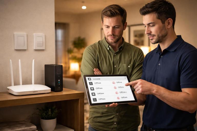
Case Study 1: “Everything Worked Yesterday” After ISP Router Swap
Scenario
A homeowner reports that smart switches still control loads locally, but app control and voice control stopped after the ISP replaced the router. Some devices appear “offline,” others respond slowly, and automations fail intermittently.
Root cause patterns (what commonly causes this)
- SSID or password changed; devices are still bound to the old network credentials.
- 2.4 GHz disabled or separated; certain devices only join 2.4 GHz.
- New router uses different LAN subnet; local integrations (hubs, bridges) can’t find devices.
- Client isolation or “IoT network” settings block device-to-hub traffic.
- DHCP lease changes cause IP-based integrations to break (e.g., local API endpoints, NVRs, some bridges).
Step-by-step field workflow
1) Establish what still works without the network. Confirm local paddle control, dimming behavior, and any hardwired sensor-to-load functions. This separates electrical issues from network/commissioning issues.
2) Identify the control architecture. Determine whether the home uses a hub (Zigbee/Z-Wave), Wi-Fi-only devices, or a mix. Ask: “What is the single point of coordination?” (e.g., a hub, bridge, or controller).
- Listen to the audio with the screen off.
- Earn a certificate upon completion.
- Over 5000 courses for you to explore!

Download the app
3) Verify router settings that affect IoT. Check that 2.4 GHz is enabled, SSID and password match what devices were commissioned to, and that any “AP isolation,” “guest network,” or “IoT VLAN” rules allow hub-to-device communication.
4) Stabilize addressing for critical local integrations. If the system includes local controllers, bridges, or NVRs, assign DHCP reservations so their addresses don’t drift. If the platform requires static IPs, document them and ensure they are outside the DHCP pool.
5) Rejoin devices in a controlled order. Start with the hub/bridge, then mains-powered repeaters (if applicable), then battery devices. For Wi-Fi devices, rejoin them room-by-room to avoid confusion and to keep naming consistent.
6) Validate automations and voice control last. Once devices are online and controllable in the primary app, then validate automations, scenes, and voice assistants. This prevents chasing “automation problems” that are really “device offline” problems.
Checklist: Router swap / network change readiness
- Record SSID, password, and whether devices require 2.4 GHz.
- Record hub/bridge/controller model, IP address method (DHCP vs reserved), and physical location.
- Confirm router features: band steering behavior, client isolation, guest network separation.
- Confirm the homeowner knows which app is the “source of truth” for device management.
- Provide a “network change procedure” one-pager: what to do first, what not to reset, and who to call.
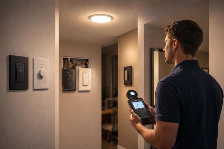
Case Study 2: Mixed Manufacturer Dimmers Causing Random Flicker Complaints
Scenario
Home has multiple dimmers installed over time. Homeowner reports random flicker on certain LED fixtures, especially at low levels, and only in some rooms. The complaint is inconsistent: “It’s fine for weeks, then it acts up.”
Root cause patterns
- Different dimming methods across devices (leading-edge vs trailing-edge vs 0–10 V driver control) applied inconsistently to similar loads.
- Firmware differences and default dimming curves not tuned for the fixture/driver.
- Minimum trim not set; low-end instability shows up as flicker.
- Multiple control points or scenes set to very low levels that are below stable driver operation.
- Line noise from other loads on the same branch affecting sensitive drivers.
Step-by-step field workflow
1) Categorize the load type per circuit. Identify whether the dimmer is controlling screw-in lamps, integrated LED fixtures, or remote drivers. Note driver brand/model where accessible.
2) Standardize dimmer configuration per load family. For each problem circuit, confirm the dimmer’s mode (if selectable) and set it to the recommended method for the load. If the dimmer supports a “LED” mode or adaptive mode, verify it is enabled.
3) Set low-end and high-end trims. Adjust minimum brightness to the lowest stable level without flicker, and set maximum if the fixture overdrives or buzzes at full output. Document the trim values.
4) Validate scene levels. Check automation/scene presets that set lights to 1–5%. If the system frequently calls those levels, raise them to the stable minimum.
5) Confirm behavior under worst-case conditions. Test at low level while other known noisy loads operate (bath fan, vacuum, microwave, EVSE if present). If flicker correlates, consider isolating sensitive lighting circuits or using fixtures/drivers with better immunity.
Checklist: Dimmer/LED stability commissioning
- Record fixture/driver model and dimmer model per circuit.
- Confirm dimming method/mode is correct for the load.
- Set and document low-end trim and high-end trim.
- Review scenes/automations for ultra-low setpoints.
- Test at multiple levels (10%, 25%, 50%, 100%) and during operation of other household loads.
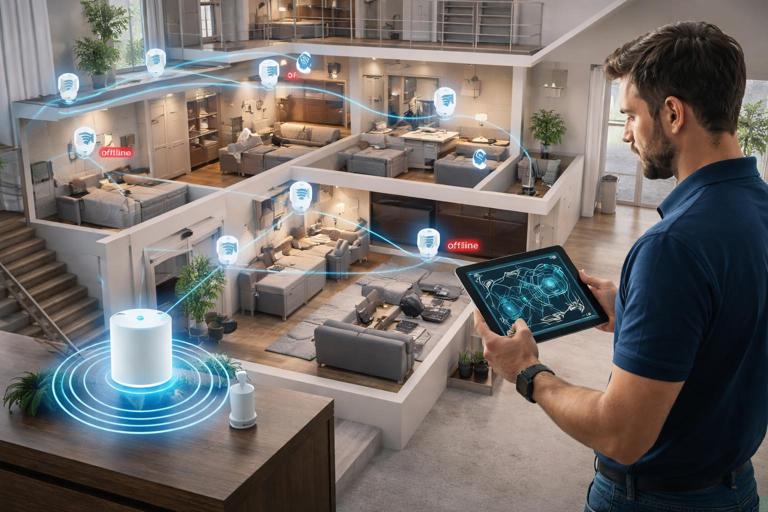
Case Study 3: “Phantom Offline” Devices in a Large Home with a Hub
Scenario
A larger home uses a hub-based system. Some devices show offline in the app, then come back. Battery sensors miss events. Homeowner reports it’s worse after a remodel when devices were added.
Root cause patterns
- Mesh network weakened by removal/relocation of powered repeaters (devices moved, circuits changed, or powered devices replaced with non-repeating models).
- Hub location changed to a less central spot due to furniture or AV cabinet placement.
- Too many devices joined quickly without allowing the mesh to settle.
- Interference from new equipment (AV racks, metal enclosures, mirrors, appliances).
- Battery devices paired in the wrong location (paired near hub, then installed far away) leading to poor route selection.
Step-by-step field workflow
1) Map the system physically, not just in the app. Walk the home and mark hub location, repeating devices (mains-powered), and end devices (battery). Note construction changes (new tile, mirrors, metal studs, radiant barriers).
2) Verify hub placement fundamentals. Place hub away from dense metal, large AV equipment, and Wi-Fi routers stacked together. Aim for central location and reasonable height.
3) Rebuild mesh intentionally. Add or confirm enough mains-powered repeaters distributed across floors and wings. If the platform supports it, run a mesh heal/repair after changes, and allow time for route optimization.
4) Re-pair critical battery devices in place. For sensors that miss events, exclude and include them at their installed location (or use the platform’s recommended method for in-place pairing). This encourages correct route selection.
5) Validate event delivery, not just “online status.” Trigger sensors repeatedly and confirm events appear promptly in the hub logs/app. “Online” can be misleading; event latency is what matters for automations.
Checklist: Hub-based system expansion
- Confirm hub location: central, elevated, not inside metal/AV cabinet.
- Count mains-powered repeaters per area; ensure coverage across floors.
- After adding devices, allow stabilization time and run mesh optimization if supported.
- Pair battery sensors in place when possible.
- Verify event latency and automation triggers in each zone.
Case Study 4: Service Call After a Power Event (Brownout/Outage/Generator Transfer)
Scenario
After a storm outage, some smart devices behave oddly: a few are unresponsive, some lights come on unexpectedly, and schedules are wrong. The homeowner may also have backup power (generator or battery) that changed how the home rides through outages.
Root cause patterns
- Devices stuck in a faulted state after undervoltage or rapid cycling.
- Controller/hub reboot order issues: hub comes up before network, or devices come up before hub.
- Cloud-dependent schedules drift or fail when time sync is delayed.
- Backup power changes which circuits remain energized, creating partial system availability and confusing “expected behavior.”
Step-by-step field workflow
1) Determine the power topology during the event. Ask whether the home was on utility, generator, or battery at the time issues began. Identify which circuits were backed up and which were not.
2) Perform a controlled reboot sequence. Power-cycle in a logical order: network infrastructure (modem/router/APs) first, then hub/controller/bridges, then end devices as needed. Avoid rapid cycling; allow full boot and stabilization.
3) Check time and location settings. Confirm the controller and router have correct time (NTP). Incorrect time causes schedules, sunrise/sunset events, and occupancy logic to misbehave.
4) Validate “power restore behavior” settings. Many devices have settings for what happens after power returns (restore last state, turn on, turn off). Align these with homeowner expectations, especially for bedrooms, exterior lighting, and safety-critical areas.
5) Simulate a brief outage if permitted. With homeowner approval and safe conditions, simulate a controlled power interruption to the relevant circuits and verify the system returns to the intended state.
Checklist: Post-outage reliability verification
- Document which circuits are backed up and expected behavior during backup operation.
- Verify router/AP uptime and time sync.
- Confirm hub/controller boots cleanly and reconnects to devices.
- Check device “power restore state” settings for key loads.
- Test one controlled outage/restore sequence and confirm lighting states and automations.
Case Study 5: New Construction Handoff Fails Because of Naming and Zone Confusion
Scenario
Everything is wired and works, but the homeowner is frustrated: voice commands control the wrong lights, scenes are confusing, and service calls keep coming in for “it doesn’t work,” which is really “it’s not organized.”
Root cause patterns
- Device names don’t match room names or physical labels.
- Duplicate names across floors (e.g., “Hall Light” appears multiple times).
- Scenes created without a consistent standard (some by room, some by activity, some by time).
- Keypads or multi-button controls not aligned with how the homeowner thinks about the space.
Step-by-step field workflow
1) Establish a naming standard before final programming. Use a consistent pattern such as: Floor-Room-Load (e.g., “1F Kitchen Pendants,” “2F Primary Bath Vanity”). Keep names short but unique.
2) Align physical labels and digital names. If a device is labeled in the panel or at the device location, ensure the app name matches. Mismatches create long-term service friction.
3) Build zones and scenes from a homeowner interview. Ask how they use the home: “Which lights do you want together?” “What should happen when you say ‘Goodnight’?” Translate that into a small set of predictable scenes.
4) Validate voice control semantics. Test common phrases in each room. Adjust names to avoid collisions (e.g., “Kitchen” vs “Kitchen Island”).
5) Create a service-friendly map. Provide a one-page zone map: room names, device names, and what each keypad button does. This reduces future calls and speeds remote support.
Checklist: Organization and usability commissioning
- Adopt a naming convention and apply it consistently.
- Ensure uniqueness across the entire property.
- Match physical labels to app/controller names.
- Limit scenes to a manageable set; verify each has a clear purpose.
- Test voice commands in real rooms with doors closed/open and typical background noise.
Field Checklists You Can Use on Every Smart Home Job
1) Pre-commissioning walk-through checklist (before you “turn on features”)
- Confirm all devices are physically installed, secured, and accessible for service (no buried junctions, no blocked hubs/bridges).
- Confirm the homeowner’s network information is available (SSID/password) and that the network equipment is installed and powered.
- Confirm you have admin access to required apps/controllers for commissioning (avoid commissioning under a temporary guest account).
- Identify special areas: exterior, bathrooms, stairways, bedrooms, mechanical rooms, and any spaces needing conservative “power restore” behavior.
- Identify any third-party integrations expected (voice assistants, security, AV, energy monitoring) so you can validate them in the right order.
2) Device bring-up checklist (repeat per room/zone)
- Verify local control first (manual on/off/dim/relay function) before pairing.
- Pair/join the device and immediately rename it using the naming standard.
- Assign it to the correct room/area in the controller/app.
- Set device-specific parameters that affect behavior (fade rate, default level, indicator LED behavior, power restore state).
- Test control from: local device, app, and any wall control/keypad that should operate it.
3) Automation validation checklist (functional testing, not just “it exists”)
- For each automation, test the trigger condition in real conditions (walk test occupancy, open/close contact, time-based event).
- Confirm the action affects the intended devices only (no unintended cross-room actions).
- Confirm timing: delays, fade times, and off-timers match expectations.
- Test edge cases: manual override (turning a light off during an “on” automation), and re-trigger behavior (does it restart timers or ignore?).
- Document automation purpose in plain language (useful for future service).
4) Resilience checklist (reduce callbacks after changes)
- Verify what happens after power loss and restore for key circuits (bedrooms, exterior, safety lighting).
- Verify what happens after internet loss (local control, hub control, schedules if local).
- Verify what happens after router reboot (devices reconnect, controller reconnects).
- Ensure critical hubs/bridges/network gear are on stable power (consider UPS where appropriate and permitted).
- Confirm firmware is updated only when you can validate afterward; avoid “update everything” at the end of the day without time to retest.
5) Serviceability checklist (make future troubleshooting fast)
- Confirm each device is identifiable physically (location notes, photos, or a map).
- Record hub/controller location and how to access it (cabinet, shelf, power source).
- Record which integrations exist and which account owns them (homeowner vs installer).
- Store a “known good” baseline: key settings, trims, and any special parameters.
- Provide a short “what changed?” log when you leave (new devices added, scenes modified, firmware updated).
Practical Templates (Copy/Paste) for Field Notes
Device record template
Room/Area: ____________________________ Floor: ________ Date: ____________ Installer: ____________ Device Type: __________________________ Manufacturer/Model: ___________________ Load Controlled: ______________________ Circuit/Breaker ID: ___________________ App/Controller Name: __________________ Firmware Version (if applicable): ______ Key Settings: - Power restore state: ________________ - Fade rate: _________________________ - Min/Max trim: ______________________ Notes/Exceptions: _____________________Automation test template
Automation Name: _______________________ Trigger: ______________________________ Conditions: ___________________________ Actions: ______________________________ Test Steps Performed: 1) _________________________________ 2) _________________________________ Expected Result: _______________________ Actual Result: _________________________ Pass/Fail: ______ Adjustments Made: ______________________Network/hub snapshot template
Primary Router/AP: ______________________ SSID(s): ______________________________ 2.4 GHz Enabled: Yes/No Guest/IoT Network Used: Yes/No Isolation Enabled: Yes/No Hub/Controller: ________________________ Location: ______________________________ IP Method: DHCP / Reservation / Static Reserved IP (if any): __________________ Notes: _________________________________Field Habits That Prevent the Most Callbacks
Commission in layers, verify at each boundary
Use a consistent order: verify local device behavior, then controller/app control, then automations, then voice/integrations. If you skip layers, you can end up debugging the wrong layer (for example, chasing a voice assistant issue when the device never joined properly).
Change one variable at a time
When resolving intermittent issues, avoid making multiple changes at once (firmware update plus router settings plus device replacement). Make one change, retest, and document. This is especially important when the homeowner reports “random” behavior; your job is to make the system deterministic again.
Prove reliability with repeatable tests
For critical zones (entry, stairs, exterior), run a repeat test: trigger the same action 10 times and confirm identical results. Reliability is demonstrated by repetition, not by a single successful tap.
Build for the next technician
Assume someone else will service the system later. Your checklists, naming, and templates should allow a technician to identify a device, understand its purpose, and verify expected behavior quickly without reverse-engineering the installation.