Why Placement and Power Quality Matter in Smart Homes
Smart home reliability is often determined less by the “smart” device itself and more by where it is installed, what it is installed near, and what kind of electrical environment it lives in. Device placement affects radio performance, sensor accuracy, and serviceability. Interference avoidance reduces dropouts, false triggers, and intermittent control failures that waste troubleshooting time. Power quality considerations reduce nuisance resets, premature device failure, and hard-to-diagnose problems that appear only when certain loads run (HVAC, pumps, EV charging, or motor-driven appliances).
This chapter focuses on practical placement rules, interference sources you can recognize on-site, and power quality checks/mitigations that electricians can apply during installation and service calls.
Device Placement: Physical Location, Materials, and Serviceability
General placement principles
- Place for performance and access: A device that works perfectly but is buried behind a refrigerator, inside a metal can, or above a hard-lid ceiling without an access panel is a future service problem.
- Minimize barriers between radios: Dense materials (concrete, brick, tile over cement board, plaster with metal lath) attenuate signals more than drywall and wood framing.
- Avoid metal enclosures and “metal sandwiches”: Metal boxes, steel studs, foil-faced insulation, radiant barriers, and appliance skins can create a partial Faraday cage effect.
- Respect heat and airflow: Electronics and power supplies derate with heat. Avoid mounting where ambient temperatures are high or where airflow is restricted.
- Plan for future replacement: Leave slack, label conductors, and avoid mounting devices where replacement requires disassembling cabinetry or removing heavy appliances.
Placement for common device types
Hubs, bridges, and controllers: Treat these as “network infrastructure.” Place them centrally relative to the devices they serve, elevated (e.g., on a shelf rather than on the floor), and away from large metal objects. Avoid placing them inside structured wiring cans or metal panels unless the manufacturer explicitly supports it and you have verified performance.
In-wall smart controls and modules: In-wall placement is convenient but can be radio-hostile if the box is metal or surrounded by tile/concrete. If a device supports an external antenna or remote mounting, consider it in difficult construction types. Keep line-voltage electronics away from sources of heat (near baseboard heaters, above ovens) and away from high-vibration locations.
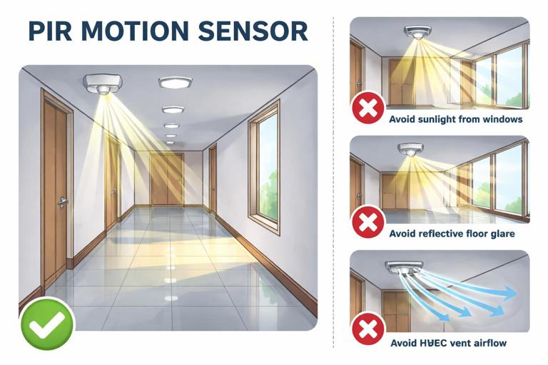
Sensors (motion, contact, leak, temperature): Sensors are only as good as their field of view and environmental conditions. Avoid direct sunlight on PIR motion sensors (false triggers), avoid mounting temperature sensors on exterior walls or near supply registers (skewed readings), and keep leak sensors where water will actually accumulate first (low points, under shutoff valves, water heater pan).
- Listen to the audio with the screen off.
- Earn a certificate upon completion.
- Over 5000 courses for you to explore!

Download the app
Smart plugs and receptacle-based controls: Ensure they are not blocked by furniture or appliances that create shielding. In kitchens and laundry rooms, avoid placing radio-dependent controls behind large metal appliances when possible; a few feet of relocation can make a major difference.
Building materials and “hidden” attenuation
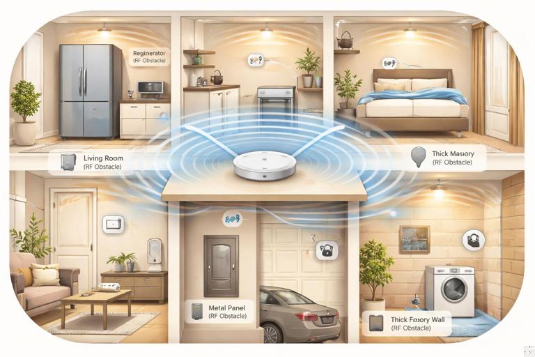
When a customer reports “it works in some rooms but not others,” the cause is often construction, not configuration. Use these rules of thumb:
- Concrete and masonry: Expect significant attenuation. Place hubs on the same floor when possible and avoid crossing multiple concrete walls.
- Tile and stone: Tile over cement board can behave like a partial RF barrier. Bathrooms can be challenging; consider placing repeaters/routers outside the bathroom but nearby.
- Foil-backed insulation and radiant barriers: These can reflect or absorb RF. Attics with radiant barrier can isolate upstairs devices from downstairs hubs.
- Metal lath/plaster and steel studs: These can create unpredictable dead zones. If you see plaster walls or steel framing, assume you may need closer spacing between devices or alternate placement.
Service loops, labeling, and access panels
Even when placement is driven by aesthetics, you can still install for serviceability:
- Leave a small service loop where permitted so a device can be pulled out of a box without straining conductors.
- Label conductors and device locations in the panel schedule or as-built notes (especially for hidden modules).
- For ceiling-mounted drivers/controllers, provide an access panel or locate them in an accessible junction area, not buried above drywall.
Interference Avoidance: What Causes Dropouts and False Behavior
Interference categories you can identify on-site
Most smart home “interference” complaints fall into one (or more) of these categories:
- RF interference: Competing transmitters, poor placement, or reflective/absorptive materials.
- Electrical noise (conducted EMI): Noise injected onto branch circuits by certain loads or power supplies.
- Magnetic/electrical fields: Proximity to motors, transformers, and high-current conductors.
- Sensor interference: Environmental factors (sunlight, HVAC drafts, pets, reflective surfaces) causing false triggers or bad readings.
Common RF interference sources in homes
- Wi-Fi congestion: Neighboring networks, mesh nodes too close together, or poor channel planning can reduce reliability for Wi-Fi devices and also raise the noise floor for nearby electronics.
- 2.4 GHz “noisemakers”: Microwave ovens (when running), some older cordless phones, baby monitors, and certain video senders can disrupt nearby devices.
- USB 3.0 and poorly shielded cables: USB 3.0 devices and cables can radiate in the 2.4 GHz band. A hub placed next to a USB hard drive or certain mini PCs can suffer intermittent issues.
- Metal appliances and mirrors: Refrigerators, ranges, metal ductwork, and large mirrors can reflect or block signals, creating multipath and dead spots.
Separation distances and placement heuristics
Use practical spacing rules to reduce interference without overengineering:
- Keep hubs/bridges at least a few feet from Wi-Fi routers, cordless phone bases, and large AV receivers to reduce near-field coupling and power-supply noise interaction.
- Avoid placing radio hubs directly behind TVs or inside media cabinets packed with streaming boxes and power bricks; move them to an open shelf edge or above the cabinet.
- Do not mount sensitive sensors immediately adjacent to motor housings (garage door openers, air handlers) or transformer enclosures.
Sensor placement to avoid false triggers
PIR motion sensors: Avoid aiming at windows with direct sun, reflective floors that catch sun patches, or HVAC vents that blow warm/cool air across the sensor. In hallways, mount to avoid “looking” directly at stair landings where temperature gradients can be strong.
Door/window contacts: Avoid mounting where metal frames can reduce range. Ensure alignment tolerances account for seasonal movement (wood swelling) and door slam vibration.
Temperature/humidity sensors: Keep away from exterior doors, supply registers, and kitchens/baths unless you are intentionally measuring those zones. A sensor mounted above a refrigerator or near a recessed can light will read high.
Power Quality Considerations: The Electrical Environment Smart Devices Need
What “power quality” means in a smart home context
Power quality is the combination of voltage stability, waveform cleanliness, grounding/bonding integrity, and transient behavior that determines whether electronics operate reliably. Smart devices often include switching power supplies, microcontrollers, and radio modules that can reset or misbehave when exposed to sags, spikes, high harmonic content, or excessive electrical noise.
Power quality issues commonly show up as:
- Random device reboots or “offline” events that correlate with HVAC starting, a well pump cycling, or a compressor turning on.
- Flicker complaints that coincide with dimming or motor loads.
- Touch controls that become unresponsive or behave erratically.
- Nuisance tripping of AFCI/GFCI devices when certain electronic loads operate (often a compatibility/noise issue rather than a wiring fault).
Key power quality problems and what causes them
Voltage sags (brownouts): Short-duration drops when large loads start (compressors, pumps, some power tools). Sensitive electronics may reset if their internal DC bus drops below threshold.
Transients/surges: Fast spikes from switching inductive loads, utility events, or lightning. Even when they do not destroy equipment, they can degrade power supplies over time.
Conducted EMI: Noise riding on the line from variable-speed drives, cheap LED drivers, phone chargers, and certain appliances. This can interfere with device power supplies and, in some cases, with signaling methods used by controls.
Harmonics and waveform distortion: Nonlinear loads (many modern electronics) draw current in pulses, distorting the current waveform and sometimes contributing to neutral heating and voltage distortion. In a typical residence this is usually manageable, but it can compound issues when many electronic loads share a circuit.
Neutral and grounding integrity issues: Loose neutrals, shared neutrals with poor terminations, or high-impedance grounding paths can create unstable reference points and noise susceptibility. (This chapter focuses on symptoms and checks rather than re-teaching termination methods.)
Practical Step-by-Step: Placement and Interference Walkthrough on a Job
Step 1: Do a quick “RF and noise” site scan
- Identify likely RF blockers: masonry walls, metal lath, radiant barrier, large mirrors, mechanical rooms with ductwork.
- Identify likely noise sources: HVAC air handler, condenser disconnect area, well pump controls, EV charger, workshop circuits, server racks, home theater stacks.
- Ask the homeowner what correlates with failures: “Does it happen when the microwave runs?” “When the heat kicks on?” “Only at night?” Correlation is a powerful diagnostic tool.
Step 2: Choose hub/controller locations intentionally
- Pick a central location relative to device density, not necessarily where the internet modem happens to be.
- Prefer open-air placement: on a shelf, not inside a metal can or behind a TV.
- Provide stable power: avoid receptacles controlled by a wall switch; avoid outlets shared with heavy, noisy loads when possible.
Step 3: Place repeaters/routers (where applicable) to “bridge” difficult areas
Even without diving into protocol specifics, the physical concept is consistent: intermediate powered devices can help extend coverage. Place these where they have good connectivity to the hub and also to the target area. Avoid placing the “bridge” device inside the dead zone itself; place it just outside, where signal is still strong.
Step 4: Validate sensor placement with real-world triggers
- Walk-test motion sensors at different times if sunlight is a factor; at minimum, simulate with a flashlight and observe susceptibility.
- For temperature sensors, compare readings to a reference thermometer after HVAC has stabilized; relocate if the sensor is influenced by drafts or radiant heat.
- For leak sensors, verify they sit at the lowest point and will contact water early (not perched on a ridge or grout line).
Step 5: Document “do not block” zones
When a device is placed for RF reasons (e.g., on top of a cabinet), note it for the homeowner: “Don’t move this behind the microwave,” “Don’t stack metal baking trays around it,” etc. Many intermittent issues are caused by later furniture rearrangement.
Practical Step-by-Step: Power Quality Checks and Mitigations
Step 1: Identify symptoms that point to power quality
- Resets at the same time daily: Often HVAC, water heater, or other scheduled load.
- Multiple devices drop together: Suggests a shared circuit sag or a shared power supply issue.
- Problems only on one circuit/area: Points to localized noise or a termination/connection issue.
- Flicker plus device issues: Suggests voltage fluctuation, loose connection, or incompatible electronic loads on the same run.
Step 2: Measure and observe under load
Static voltage readings can look fine while problems occur during load transitions. Use measurements that capture events:
- Use a true-RMS meter to check voltage at the device location and at the panel, then compare when large loads start.
- If available, use a power quality logger or scope function to capture sags/transients during compressor start or motor cycling.
- Check for excessive voltage drop on long runs by measuring at the farthest device while a known load is applied.
Step 3: Confirm terminations and shared conductor issues when symptoms match
When you see flicker, resets, or heat at devices, treat it as a potential connection problem until proven otherwise. Verify torque and integrity at relevant terminations (panel, device box, splices) and look for signs of overheating. If symptoms suggest a neutral issue (multi-device instability, odd voltage behavior), prioritize that investigation.
Step 4: Reduce conducted noise from problematic loads
Some loads are repeat offenders: certain LED drivers, inexpensive plug-in power supplies, motor controllers, and older appliances with worn brushes. Practical mitigations include:
- Relocate sensitive devices: Move hubs/controllers to a receptacle not shared with noisy loads (e.g., not on the same outlet strip as a TV, game console, and multiple power bricks).
- Separate circuits where feasible: If a critical controller shares a circuit with a motor load that causes sags/noise, consider moving the controller to a different circuit or adding a dedicated receptacle circuit for network/control equipment.
- Add line filtering where appropriate: Use appropriately rated EMI filters or power conditioners for sensitive control equipment (especially for hubs, routers, and controllers). Ensure any added device is listed and installed per manufacturer instructions.
- Address the source: Replace a noisy driver/power supply rather than masking it, when practical.
Step 5: Surge protection strategy for smart homes
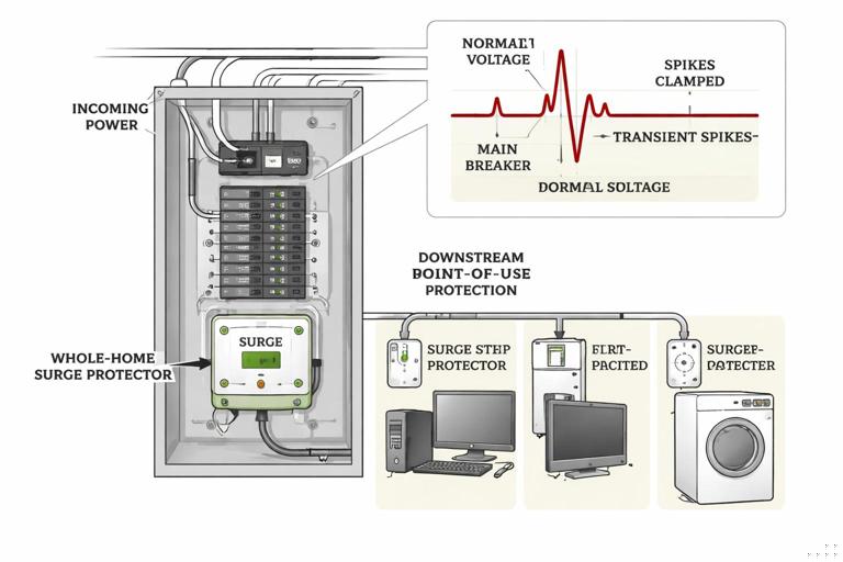
Smart homes often have more electronics distributed throughout the building, increasing exposure to transients. A layered approach is common:
- Service/whole-home surge protective device (SPD): Helps clamp larger transients entering from the utility or generated by large loads.
- Point-of-use protection: For sensitive hubs, routers, and AV/network stacks, use quality point-of-use protection to reduce residual surges and noise.
- Protect low-voltage/data paths: Surges can travel on coax, Ethernet, and other conductors. Use listed protectors where required and maintain proper bonding practices.
When installing SPDs, keep lead lengths short and routing direct to reduce let-through voltage. Verify bonding/grounding integrity because surge devices rely on a solid reference path.
Step 6: UPS selection for controllers and network gear
Many smart home failures during “power events” are not long outages but brief sags or momentary interruptions. A UPS can bridge these events for critical gear:
- Put the internet modem/ONT, router, and smart home controller on a UPS so automations and remote access remain stable.
- Choose a UPS with appropriate capacity and output waveform for the connected equipment; some power supplies are sensitive to stepped approximations.
- Mount/locate the UPS where it has ventilation and is accessible for battery replacement.
Coordination Between Placement and Power Quality
Don’t co-locate radios with noisy power equipment
Even if a location is physically central, placing a hub next to a panelboard, large transformer, EVSE, or motor controller can expose it to both RF shadowing (metal) and conducted/radiated noise. A better approach is often a nearby interior wall location with clean power and fewer metal obstructions.
Keep power supplies and “wall warts” under control
Clusters of plug-in power supplies can inject noise and create heat buildup. Practical tactics:
- Use a ventilated power strip with spacing, not a tightly packed cube tap.
- Separate the hub/controller power supply from high-current adapters (laptops, printers, amplifiers).
- If a specific adapter is suspected, swap with a known-good listed supply of the correct rating and re-test.
Troubleshooting Scenarios (Field-Style Examples)
Scenario 1: Devices in a bathroom go offline intermittently
Likely contributors: Tile/cement board attenuation, mirrors, and a hub located across multiple walls. Exhaust fan motor noise can also contribute if the device shares the same circuit and has a marginal power supply.
Practical approach:
- Relocate or add a powered device just outside the bathroom to improve coverage through the doorway.
- Verify the bathroom device is not in a metal box or behind a mirror cabinet.
- Check whether failures correlate with the fan running; if yes, evaluate conducted noise and consider separating the hub/controller power from that circuit.
Scenario 2: Smart controls reset when the HVAC starts
Likely contributors: Voltage sag on a shared circuit, loose termination, or a marginal power supply in the control device.
Practical approach:
- Measure voltage at the affected device while the HVAC starts; compare to panel voltage.
- Inspect/verify terminations on the affected circuit path (device box, splices, panel).
- If the controller/hub is on the same circuit as a motor load, move it to a cleaner circuit or add UPS support for the controller/network gear.
Scenario 3: Intermittent control issues near the media center
Likely contributors: RF shadowing behind a TV, USB 3.0 noise, dense power brick cluster, and metal rack components.
Practical approach:
- Move the hub/bridge to the front edge of the cabinet or to an open shelf, away from the TV backplane.
- Separate the hub from USB 3.0 hard drives and unshielded cables.
- Place the hub power supply on a cleaner strip and reduce adapter crowding.
Installation Checklist: Placement, Interference, and Power Quality
Placement checklist
- Hub/controller centrally located, elevated, open-air, not in metal enclosure.
- Devices not blocked by appliances, mirrors, or dense masonry where avoidable.
- Sensors mounted away from sunlight, drafts, and heat sources; validated by walk-test.
- Access provided for any concealed electronics; labeling/as-built notes updated.
Interference checklist
- Hubs separated from routers/AV stacks/power brick clusters by a practical distance.
- No known RF “noisemakers” immediately adjacent (microwave, USB 3.0 storage, cordless base).
- Repeaters/routers placed just outside difficult areas, not deep inside dead zones.
Power quality checklist
- Critical network/control equipment on stable power (not switched, not shared with heavy/noisy loads when possible).
- Surge protection strategy implemented (whole-home SPD and point-of-use where appropriate).
- UPS used for modem/router/controller where brief outages or sags are common.
- Voltage under load verified when symptoms suggest sag/drop issues; terminations checked when flicker/resets are reported.
// Quick diagnostic questions to ask on-site (write these on your job notes) 1) What exact event triggers the problem (HVAC start, microwave, laundry)? 2) Does it affect one device, one room, or many devices at once? 3) Did it start after a new appliance/router/TV was installed? 4) Is the hub inside a cabinet, behind a TV, or near a panel/metal rack? 5) Are there construction barriers (tile, concrete, radiant barrier) between devices?